Door control system and method for vehicles

Inactive Publication Date: 2007-03-13
DENSO CORP
View PDF11 Cites 22 Cited by
  • Summary
  • Abstract
  • Description
  • Claims
  • Application Information

AI Technical Summary

Benefits of technology

[0005]It is therefore an object of the present invention to provide a door control system and me

Problems solved by technology

However, this system takes some time to enable the vehicle driver to open the door after he touches it.
In this system, the radio device must continuously or periodically generate radio signals for communications with the electronic k

Method used


Image

  • Door control system and method for vehicles
  • Door control system and method for vehicles
  • Door control system and method for vehicles

Examples


Embodiment Construction

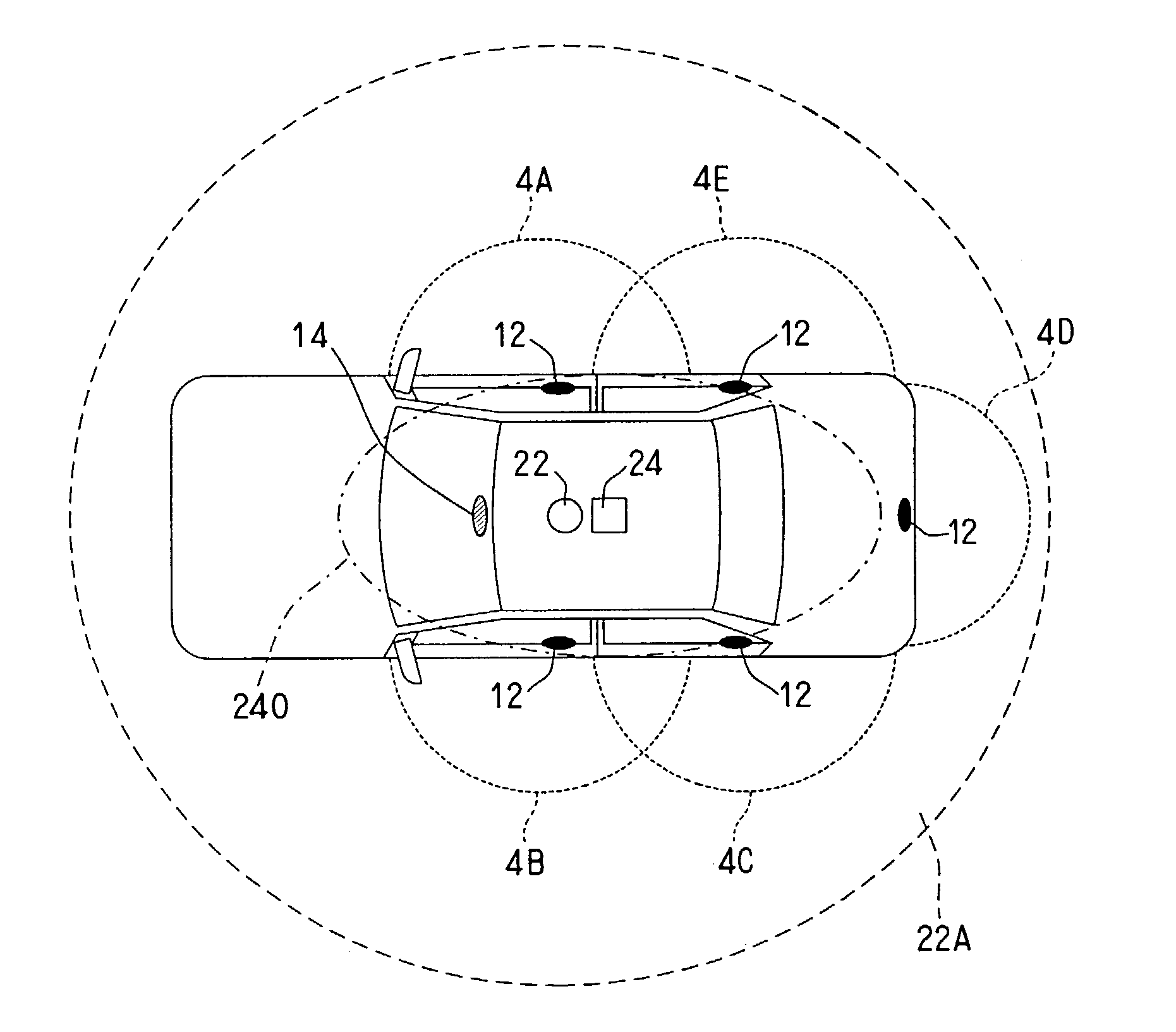
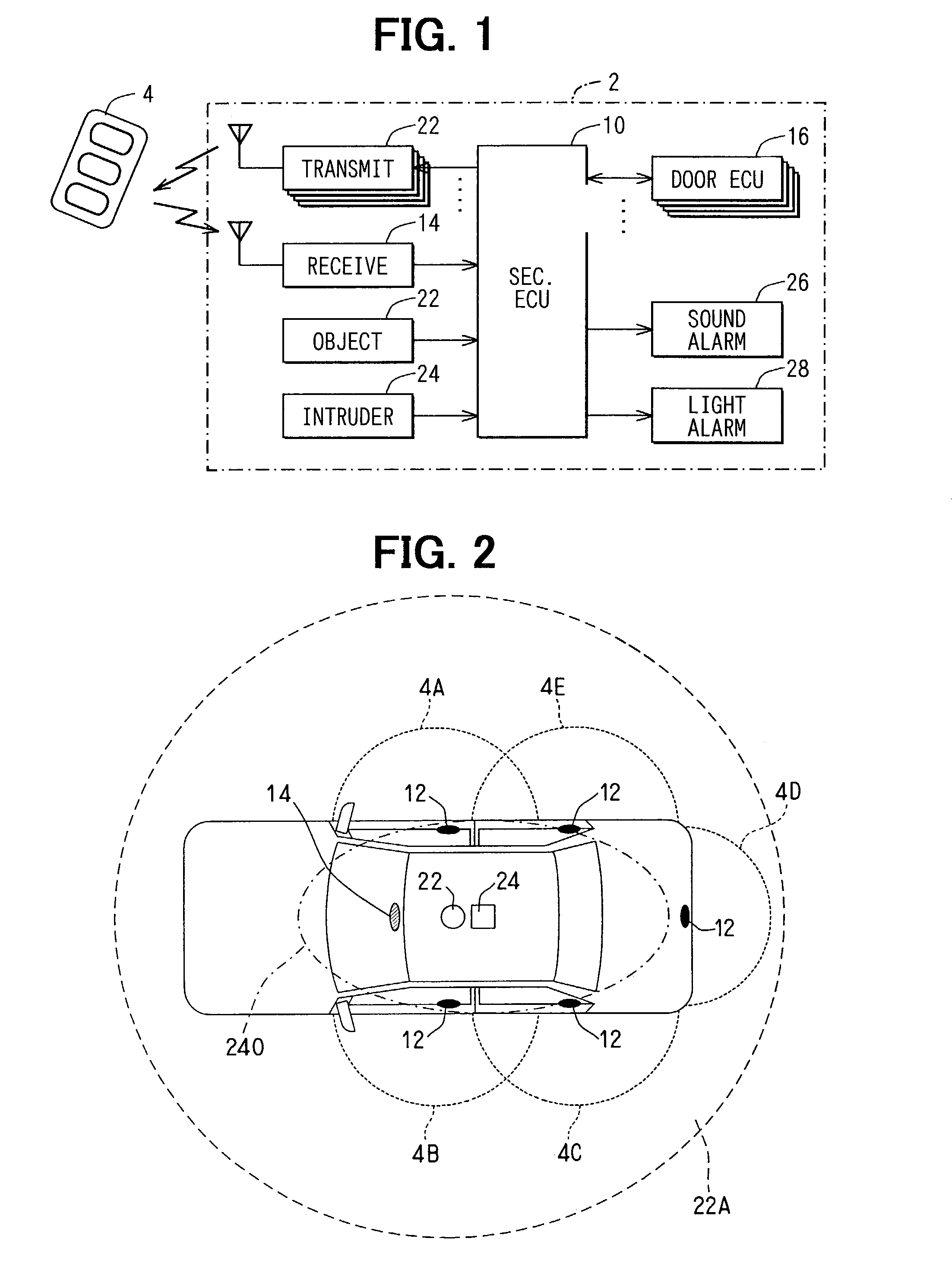
[0012]Referring first to FIG. 1, a door control system for vehicles is constructed, as a smart entry system, with a door unlocking device 2 mounted on a vehicle and an electronic key 4. The key 4 is a portable radio device carried by a vehicle driver (owner) for data communications with the device 2. The key 4 is activated by an interrogation signal transmitted from the device 2, and transmits in return its identification code (ID code) as a response signal. The ID code differs from key to key. The device 2 is primarily constructed with a security ECU (electronic control unit) 10, which monitors surrounding conditions of the vehicle, when the vehicle is held parked with its all doors being locked.

[0013]In the device 2, the ECU 10 is connected to at least one radio transmitter 12 (five transmitters in FIG. 1) for transmitting the interrogation signals for the key 4, a radio receiver 14 for receiving the response signal from the key 4, and door ECUs 16 for controlling locking and unlo...


PUM


Abstract

A door control system for vehicles has a transmitter and a receiver for detecting an electronic key in a first predetermined area around a vehicle. A control unit controls unlocking of a vehicle door by determining whether the detected electronic key is an authorized one. The door control system also has an object sensor for detecting an object entering into a second predetermined area covering and wider than the first predetermined area. The control unit activates the transmitter and the receiver only after the object sensor detects the object in the second predetermined area, thereby reducing power consumption.

Description

CROSS REFERENCE TO RELATED APPLICATION[0001]This application is based on and incorporates herein by reference Japanese Patent Application No. 2001-353472 filed on Nov. 19, 2001.FIELD OF THE INVENTION[0002]The present invention relates to a door control system and method for vehicles, which automatically drives locked vehicle doors to unlocked condition or to unlock standby condition through radio communication with an electronic key carried by a vehicle driver.BACKGROUND OF THE INVENTION[0003]As keyless entry systems for vehicles, which automatically unlock vehicle doors without mechanical key operation, a smart entry system is proposed. In one smart entry system, a radio communication device (radio transmitter / receiver) mounted in a vehicle starts its communications with an electronic key carried by a vehicle driver only after the vehicle driver manipulates a door from the exterior side. This system drives the doors to the unlock standby condition, when the electronic key is confir...

Claims


Application Information

Patent Timeline
IPC IPC(8): H04Q9/00B60R25/10G08C19/00E05B49/00B60R25/01B60R25/24B60R25/30B60R25/31B60R25/40G07C9/00
CPCB60R25/1004B60R25/246G07C9/00309G07C2209/63G07C2009/00373G07C2009/00793G07C2009/00333
Inventor SHIMOMURA, TOSHIO
Owner DENSO CORP
Why Eureka
Try Eureka