
Piezoelectric ceramic composition and piezoelectric actuator for ink-jet head based on use of the same

a technology of piezoelectric actuator and piezoelectric ceramic, which is applied in the direction of electrical equipment, device material selection, printing, etc., can solve the problem of large head-driving circuit, achieve high degree of high speed response performance, reduce the mechanical quality factor (q value) of the actuator and the sensor, and consume less electric power

Inactive Publication Date: 2005-01-18
BROTHER KOGYO KK
View PDF26 Cites 3 Cited by
  • Summary
  • Abstract
  • Description
  • Claims
  • Application Information

AI Technical Summary

Benefits of technology

The present invention has been made in order to dissolve the problems involved in the conventional technique as described above, an object of which is to provide a piezoelectric ceramic composition which makes it possible to bring about a large strain amount while suppressing the relative dielectric constant, and a piezoelectric actuator which is composed of such a piezoelectric ceramic composition and which is preferably usable for a variety of ways of use, especially for an ink-jet head.
When the composition of the present invention is used for the way of use of actuators and sensors, the composition may further contain La in a ratio of 0.3 to 0.5% by weight as calculated by conversion into an oxide represented by La2O3. In this case, it is possible to lower the mechanical quality factor (Q value) of the actuator and the sensor.
According to a second aspect of the present invention, there is provided a piezoelectric actuator which is formed of the piezoelectric ceramic composition of the present invention. The actuator of the present invention has a high degree of high speed response performance, and the actuator consumes less electric power, because the actuator is formed by using the composition of the present invention.
According to a third aspect of the present invention, there is provided an ink-jet head comprising the piezoelectric actuator of the present invention and a cavity plate. The ink-jet head makes it possible to perform high speed printing, the ink-jet head consumes less electric power, and the ink-jet head can be miniaturized, because the ink-jet head uses the piezoelectric actuator of the present invention.

Problems solved by technology

For example, a problem arises such that the head-driving circuit is large-sized.

Method used


Image

  • Piezoelectric ceramic composition and piezoelectric actuator for ink-jet head based on use of the same
  • Piezoelectric ceramic composition and piezoelectric actuator for ink-jet head based on use of the same
  • Piezoelectric ceramic composition and piezoelectric actuator for ink-jet head based on use of the same

Examples


example 1

(1) Starting Materials

Lead oxide (PbO), nickel oxide (NiO), niobium oxide (Nb2O5), titanium oxide (TiO2), and zirconium oxide (ZrO2) were used as starting materials. As for these materials, only lead oxide was weighed in an excessive amount, and the other oxides were weighed so that the stoichiometric ratio of the desired composition was obtained.

(2) Mixing and Heat Treatment

After mixing the respective materials, the mixture was formed to have a form of tablet, and the heat treatment was performed at 1050° C. for 1 hour in the atmospheric air. As for the method for mixing the materials, the dry mixing and the wet mixing were used in combination. The formed product after the heat treatment was treated as follows. That is, unreacted matters were dissolved with an aqueous acetic acid solution of 1 N, and particles were separated by means of the filtration operation, followed by being dried.

(3) Forming and Sintering

Subsequently, the obtained particles were mixed with an appropriate amou...

example 2

A piezoelectric ceramic composition according to Example 2 was prepared in the same manner as in Example 1 except that La2O3 as an additive was weighed and mixed in an objective amount based on the composition to be obtained after the sintering, in addition to lead oxide (PbO), nickel oxide (NiO), niobium oxide (Nb2O5), titanium oxide (TiO2), and zirconium oxide (ZrO2) as the starting materials, and the sintering was performed at 1260° C. for 3 hours when the respective materials were sintered.

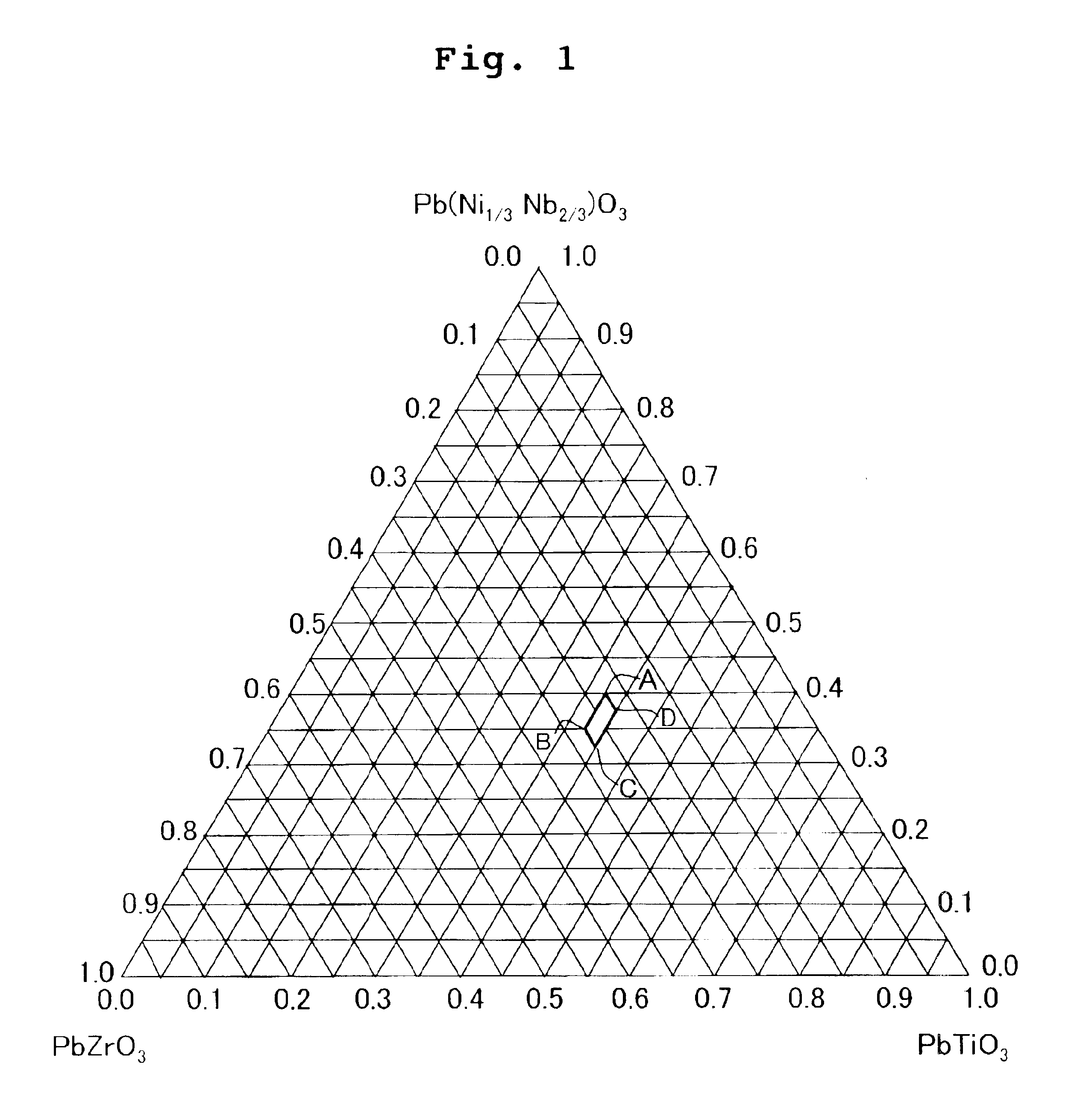
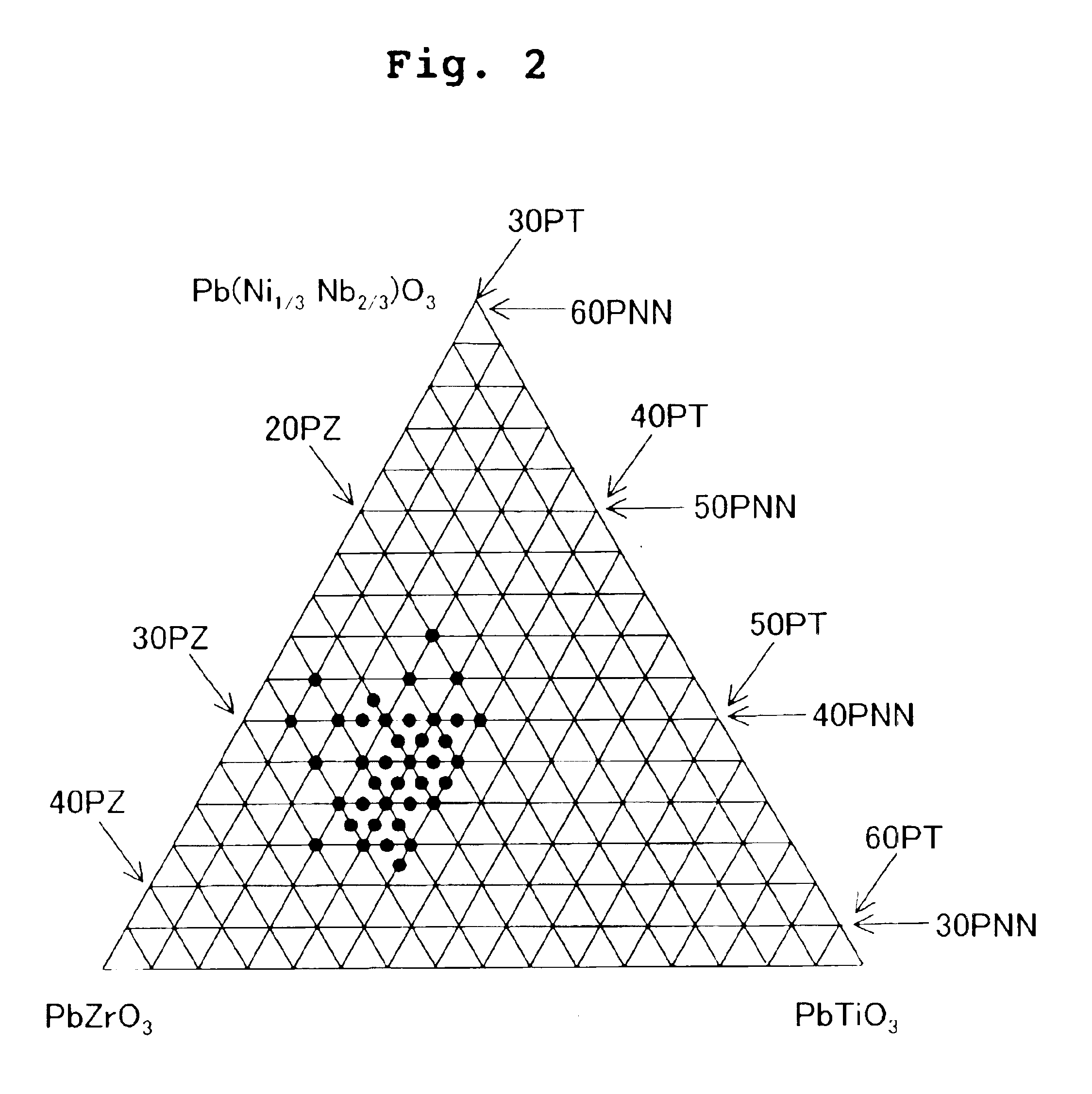
The piezoelectric ceramic composition according to Example 2 is represented by Sample Nos. 40 to 43 shown in Table 1. The basic composition of PNN-PT-PZ was the composition including PNN of 37 molar %, PT of 38 molar %, and PZ of 25 molar % (Sample No. 25) in which the relatively high piezoelectric displacement d33 was obtained in the area surrounded by Point A, Point B, Point C, and Point D as described above, to which La2O3 was added by 0.1% by weight (Sample No. 40), 0.3% by weight (Sample ...


PUM

PropertyMeasurementUnit
DC electric fieldaaaaaaaaaa
relative dielectric constantaaaaaaaaaa

Abstract

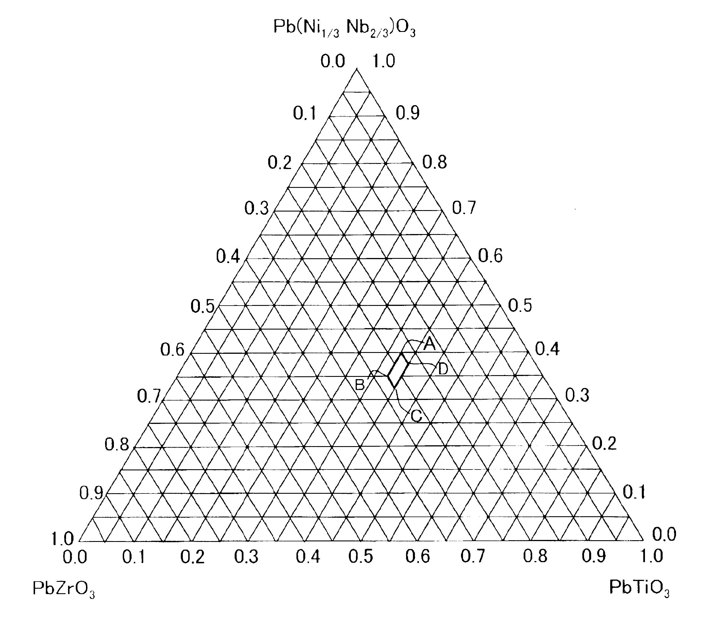
A piezoelectric ceramic composition comprises a composite perovskite type oxide of Pb(Ni1 / 3Nb2 / 3)O3 and simple perovskite type oxides of PbTiO3 and PbZrO3 as main components. The composition range of the main components exists in an area surrounded by lines for connecting respective composition points, i.e., a point A (X=40, Y=37, Z=23), a point B (X=36, Y=37, Z=27), a point C (X=33, Y=40, Z=27), and a point D (X=37, Y=40, Z=23) in a triangular coordinate system defined by apexes of Pb(Ni1 / 3Nb2 / 3)O3, PbTiO3, and PbZrO3, provided that Pb(Ni1 / 3Nb2 / 3)O3 amounts to X molar %, PbTiO3 amounts to Y molar %, and PbZrO3 amounts to Z molar %. The composition makes it possible to realize a large strain amount while suppressing the relative dielectric constant to be low. The composition is preferably usable for an piezoelectric actuator of an ink-jet head.

Description

BACKGROUND OF THE INVENTION1. Field of the InventionThe present invention relates to a ceramic composition comprising main components of Pb(Ni1 / 3Nb2 / 3)O3 as a composite perovskite type oxide and PbTiO3 and PbZrO3 as simple perovskite type oxides. In particular, the present invention relates to a piezoelectric ceramic composition which makes it possible to realize a large strain amount while suppressing the relative dielectric constant to be low, and a piezoelectric actuator for an ink-jet head based on the use of such a piezoelectric ceramic composition.2. Description of the Related ArtIn recent years, as the electronic equipment becomes small-sized and intelligent, the piezoelectric ceramic composition becomes more and more important to serve as the solid displacement element to be used for the electronic equipment. At present, a solid solution of PbTiO3—PbZrO3 (hereinafter referred to as “PZT”, if necessary), which is a solid solution composed of perovskite type oxides, i.e., PbTi...

Claims


Application Information

Patent Timeline
Patent Type & Authority Patents(United States)
IPC IPC(8): B41J2/14C04B35/495C04B35/49C04B35/499C04B35/493H01L41/18H01L41/187B41J2/045B41J2/055H01L41/09
CPCB41J2/14209H01L41/187C04B35/493C04B35/499B41J2002/14217B41J2002/14225B41J2002/14306B41J2202/20B41J2002/14491H10N30/853
Inventor MIZUNO, SHIGERU
Owner BROTHER KOGYO KK
Learn More