Method and system for detecting with radar the passage by a vehicle of a point for monitoring on a road

a technology of a vehicle and a detection point, which is applied in the direction of radio wave reradiation/reflection, measurement devices, and using reradiation, etc., can solve the problems of increasing less acceptable, requiring modifications to the road surface, and limited number of sensors which can be accommodated at a given location in the road surface, so as to save equipment costs and simplify the placement

Active Publication Date: 2007-03-13
GATSOMETER
View PDF13 Cites 13 Cited by
  • Summary
  • Abstract
  • Description
  • Claims
  • Application Information

AI Technical Summary

Benefits of technology

[0013]So as to ensure that each detection does indeed relate to only a single vehicle, the distance between the transmitting and receiving location and the point for monitoring on the one hand and the characteristic of the at least one transmitted radar beam on the other are preferably matched such that the dimension of the radar beam at the point for monitoring is of the same order of magnitude as the width of a vehicle. This prevents a plurality of vehicles being caught in the same radar beam, which could result in incorrect detection and possibly undeserved fines. This can be achieved when the distance amounts to several tens of meters and the radar beam has a beam width of several degrees.
[0014]When the road comprises a number of lanes, on each of which a specific point is to be monitored, it is recommended that for each lane a radar beam is transmitted at a related angle from the transmitting and receiving location. A plurality of lanes can thus be monitored from a single transmitting and receiving location, which results in savings in the cost of equipment and simplification of placing.

Problems solved by technology

The drawback which all said methods have in common is that they require modifications to the road surface at the location to be monitored, for instance a stop line at a traffic light.
This is increasingly less acceptable as the amount of traffic increases, all the more so because it is usually precisely at the busiest points in the road network that the detectors are required.
Furthermore, the number of sensors which can be accommodated at a given location in the road surface is limited, since there must be sufficient space between them so that they do not affect each other's operation.

Method used


Image

  • Method and system for detecting with radar the passage by a vehicle of a point for monitoring on a road
  • Method and system for detecting with radar the passage by a vehicle of a point for monitoring on a road
  • Method and system for detecting with radar the passage by a vehicle of a point for monitoring on a road

Examples


Embodiment Construction

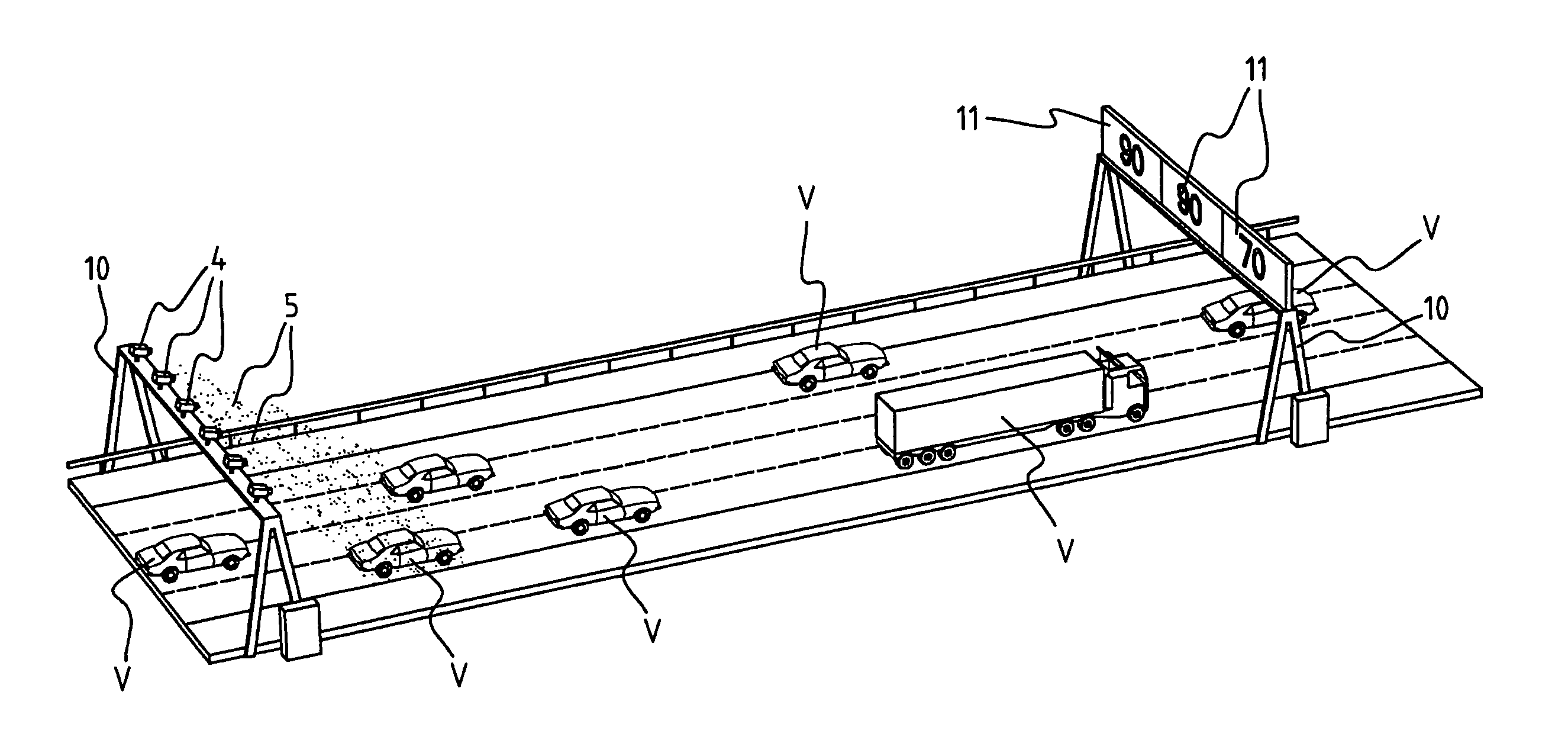
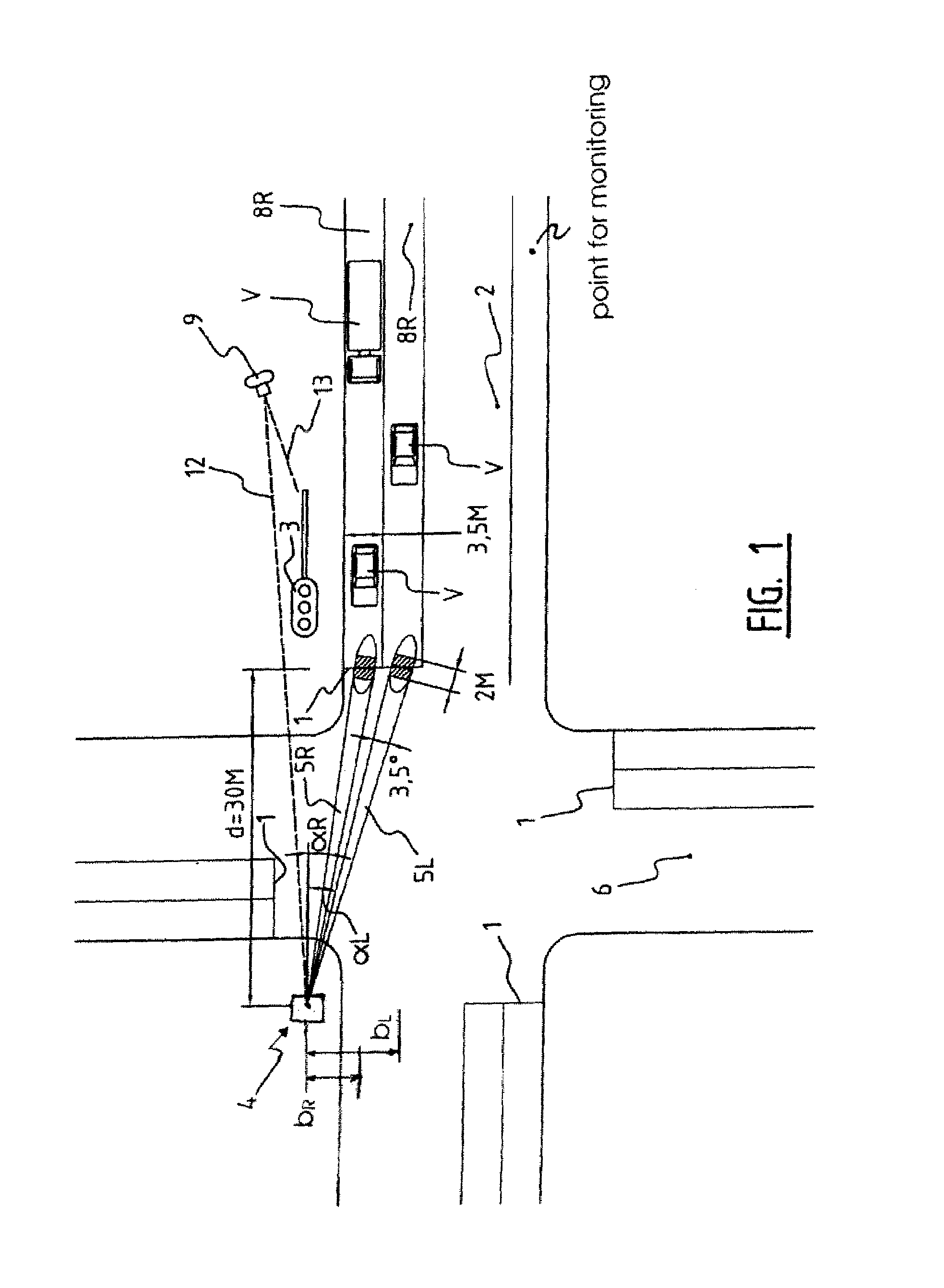
[0024]The invention relates to a system for detecting passing of a determined point for monitoring 1 on a road 2, in this case a stop line at an intersection of the road and another road 3, which intersection is protected with traffic lights 3 (FIG. 1). This detection system comprises a device 4 for transmitting a radar beam 5 to the point for monitoring 1, and receiving reflections of the radar radiation generated by passing vehicles V. The transmitting and receiving device 4, which is disposed at a location remote from stop line 1, here on the other side of the intersection, is further adapted to determine from the received reflections that a vehicle V is passing stop line 1. The transmitting and receiving device or radar device 4 transmits at a frequency of about 24 Ghz and a power of 20 dBm (EIRP).

[0025]Only a single traffic light 3 with associated detection system is drawn here, but it will be apparent that four such traffic lights and detection systems are installed at the int...


PUM


Abstract

The invention relates to a method for detecting the passage by a vehicle of a determined point for monitoring on a road, wherein from a remotely situated location a radar beam is transmitted continuously to the point for monitoring, reflections from the transmitted radar beam are received at the remotely situated location, and it is determined from the received reflections that the vehicle is passing the point for monitoring. The radar beam can herein be transmitted at an acute angle to the travel direction of the passing vehicle. The detection can be used to activate a red-light camera, to measure the speed of the vehicle or measure the traffic intensity, without sensors, for instance induction loops, having to be arranged in the road for this purpose.

Description

CROSS REFERENCE TO RELATED APPLICATIONS[0001]This application claims priority to Dutch Patent Application Number 1027018 filed Sep. 10, 2004.TECHNICAL FIELD[0002]The invention relates to a method for detecting the passage by a vehicle of a determined point for monitoring on a road. Such a method is generally known, and is used for instance in establishing traffic violations such as driving through a red light, or in measurements of traffic density, for instance for the purpose of guiding traffic in order to enhance traffic flow.BACKGROUND OF THE INVENTION[0003]In most known methods use is made of sensors which are mounted in or on the road surface. A classic example are air-filled conduits laid over the road surface which record a pressure difference when the wheels of a vehicle drive over them. Loads on the road surface by passing vehicles can also be detected using piezoelectric elements embedded in the road surface. Most widely used however are inductive detections. Here the chan...

Claims


Application Information

Patent Timeline
Patent Type & Authority Patents(United States)
IPC IPC(8): G01S13/91G01S13/58G01S13/62G01S13/92G01S13/00G01S13/04G01S13/88
CPCG08G1/01G01S13/92G01S13/04G01S13/32
Inventor JANSSEN, THEODORUS MARIA
Owner GATSOMETER
Why Eureka
Try Eureka