Method for operating an anesthesia or ventilation apparatus having a trigger function and devcie therefor

a technology of trigger function and anesthesia, which is applied in the direction of valve operation means/release devices, applications, diagnostic recording/measuring, etc., can solve the problem of reducing the drive of respiratory and respiratory functions, reducing the need for ventilation, and -dependent delay of star

Inactive Publication Date: 2009-01-08
DRAGERWERK AG
View PDF6 Cites 11 Cited by
  • Summary
  • Abstract
  • Description
  • Claims
  • Application Information

AI Technical Summary

Benefits of technology

[0005]It is an object of the invention to provide a method for operating an anesthesia or ventilation apparatus with trigger functions by means of which at least some of the above-mentioned disadvantages are avoided or can be reduced. It is also an object of the invention to provide an apparatus for carrying out the method of the invention.

Problems solved by technology

A sensitively set trigger threshold, however, has the inherent danger of a so-called self-triggering of the ventilation apparatus.
Such self-triggerings can lead to an overventilation which, inter alia, can cause a respiratory alkalosis, a reduced respiratory drive as well as an extended need for ventilation.
A disadvantage associated herewith is the time-dependent delay of the start of the triggering, a greater respiratory effort for the patient and a poorer synchronization with the known side effects associated herewith during the actual respiratory efforts of the patient.

Method used


Image

  • Method for operating an anesthesia or ventilation apparatus having a trigger function and devcie therefor
  • Method for operating an anesthesia or ventilation apparatus having a trigger function and devcie therefor
  • Method for operating an anesthesia or ventilation apparatus having a trigger function and devcie therefor

Examples


Embodiment Construction

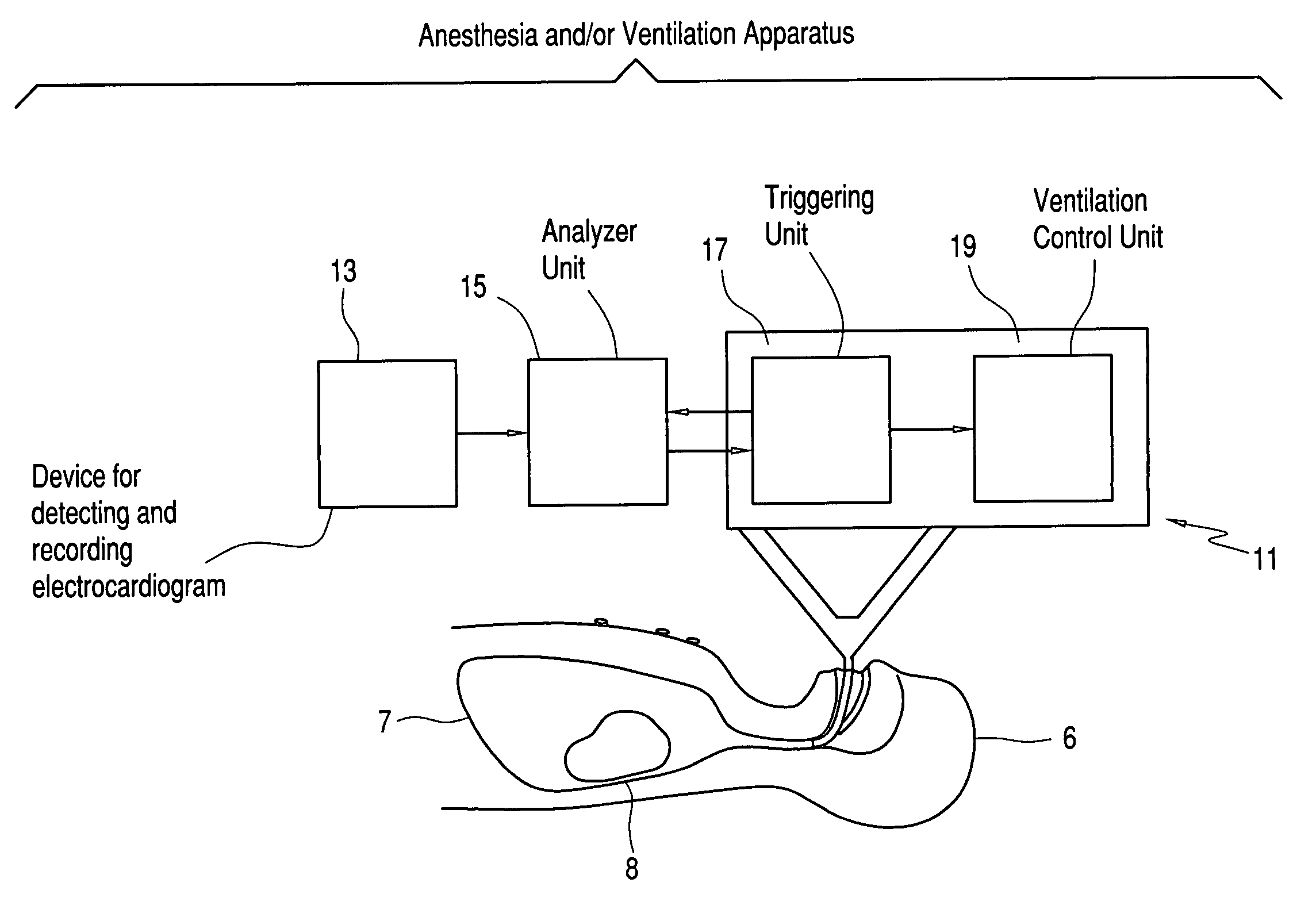
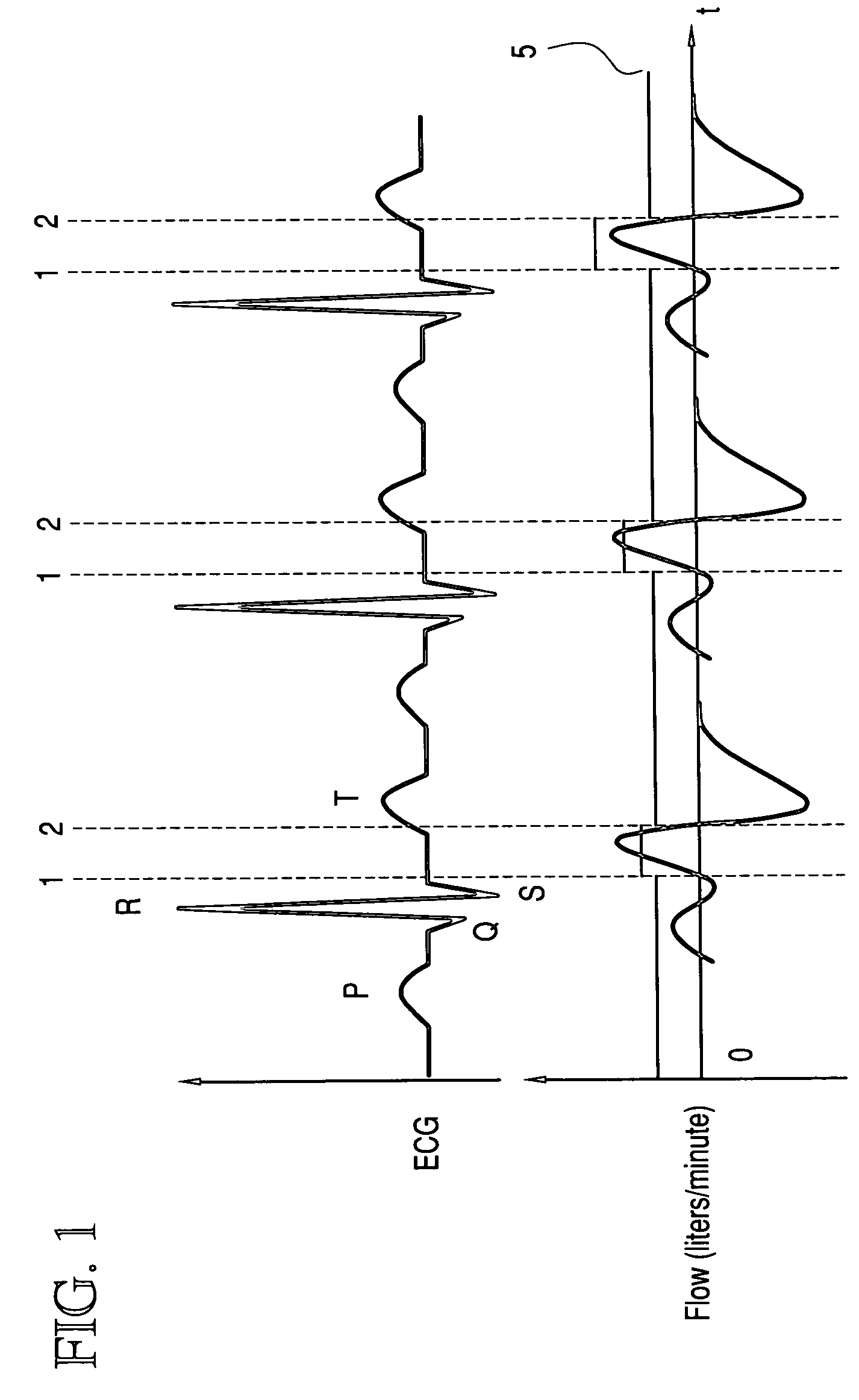
[0031]In the upper portion of FIG. 1, a schematically simplified ECG trace of a ventilated patient is shown. In the ECG trace shown, three phases are illustrated and each of these phases is identified by the numerals 1 and 2. In each phase, the time point 1 identifies the time-dependent completion of the QRS-complex and time point 2 corresponds to the occurrence of the T-wave. The flow curve of the same patient is shown in the lower portion of FIG. 1 and moves about a zero line with this flow curve being synchronized to the ECG trace. A region above the zero line corresponds to the gas take up of the patient, that is, the inhalation (mechanical or spontaneous) and a region below the zero line corresponds to the gas output or the exhalation by the patient. Reference numeral 5 identifies a flow trigger threshold or trigger threshold which is temporarily set higher to avoid cardiac self-triggering each time in a region between QRS-complex and T-wave as likewise shown in FIG. 1 in order...


PUM


Abstract

A method for operating an anesthesia/ventilation apparatus (11) avoids cardiogenic triggering of a triggered ventilation stroke. An apparatus (11) for carrying out the method of the invention is also disclosed.

Description

CROSS REFERENCE TO RELATED APPLICATION[0001]This application claims priority of German patent application no. 10 2007 031 017.1, filed Jul. 4, 2007, the entire content of which is incorporated herein by reference.BACKGROUND OF THE INVENTION[0002]From the state of the art, ventilation apparatus as well as anesthesia apparatus (referred to hereinafter as ventilation apparatus) having units for synchronizing the mechanical ventilation with spontaneous breathing efforts of the patient are known. The more sensitive the corresponding unit for triggering or executing a mechanical ventilation is adjusted, the earlier or more rapidly does the ventilation apparatus react to an inhalation effort of the patient and that much less is the required respiratory activity of the patient.[0003]A sensitively set trigger threshold, however, has the inherent danger of a so-called self-triggering of the ventilation apparatus. Here, mechanical ventilation strokes can be triggered by leakages in the hose sy...

Claims


Application Information

Patent Timeline
Patent Type & Authority Applications(United States)
IPC IPC(8): A61M16/01A61M16/00
CPCA61B5/0205A61B5/0452A61B5/4821A61M16/0051A61M2230/04A61M2016/0021A61M2016/0036A61M2205/702A61M16/01A61M16/024A61B5/349
Inventor RALFS, FRANK
Owner DRAGERWERK AG
Why Eureka
Try Eureka