Laser scanning unit

a scanning unit and laser technology, applied in the field of laser scanning units, can solve the problems of more difficult design and manufacture of f lenses, and achieve the effects of reducing the number of elements, avoiding noise produced during rotation of polygonal mirrors, and increasing scanning frequency

Inactive Publication Date: 2007-03-13
E PIN OPTICAL IND
View PDF4 Cites 73 Cited by
  • Summary
  • Abstract
  • Description
  • Claims
  • Application Information

AI Technical Summary

Benefits of technology

[0008]It is therefore a primary object of the present invention to provide an improved laser scanning unit, in which a micro electronic mechanic system (MEMS) oscillatory mirror is adopted to replace the conventional rotary polygonal mirror, so that the cylindrical lens for focusing laser beams in the direction of Y-axis is omitted from the laser scanning unit to reduce the number of elements for the laser scanning unit, and the noises produced during rotation of the polygonal mirror may be avoided, and the laser scanning unit may be started for use without waiting period.
[0009]Another object of the present invention is to provide an improved laser scanning unit having a MEMS oscillatory mirror that oscillates in harmonic motion to enable bi-directional scanning. Therefore, the laser scanning unit having the same operating speed as a conventional laser scanning unit may provide a scanning speed twice as quick as the conventional laser scanning unit, which uses the polygonal mirror to enable scan only in one direction. The laser scanning unit of the present invention therefore has increased scanning frequency and improved scanning efficiency.
[0010]A further object of the present invention is to provide an improved laser scanning unit having a MEMS oscillatory mirror, so that laser beams have a central axis aligned with a mechanical center of the MEMS oscillatory mirror. (that is, an oscillating center of the MEMS oscillatory mirror) to eliminate the problem of deviation of the central axis of laser beams from the central rotation axis of the polygonal mirror existed in the conventional laser scanning unit and to enable easy design and manufacture of the fθ lens.

Problems solved by technology

Thus, it is more difficult to design and manufacture the fθ lens 16.

Method used


Image

  • Laser scanning unit
  • Laser scanning unit
  • Laser scanning unit

Examples


Embodiment Construction

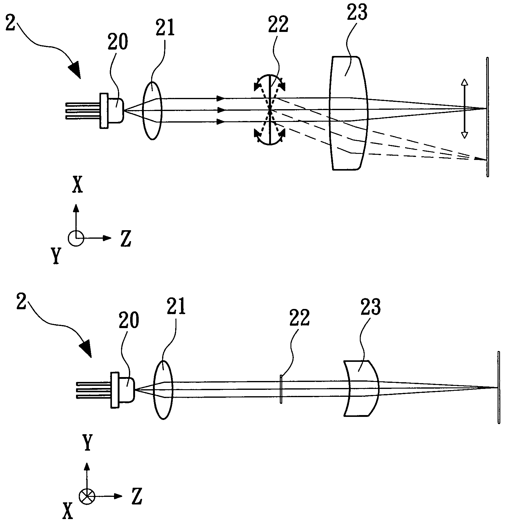
[0019]Please refer to FIGS. 2, 2A, 2B, and 2C. A laser scanning unit (LSU) 2 according to the present invention mainly includes a semiconductor laser 20, a collimator 21, a micro electronic mechanic system (MEMS) oscillatory mirror 22, and an fθ lens 23. The laser scanning unit 2 is characterized in that the MEMS oscillatory mirror 22 substitutes for the rotary polygon mirror 14 in the conventional laser scanning unit 1, so that laser beams emitted from the semiconductor laser 20 pass the collimator 21 to form parallel beams, which are directly projected onto the MEMS oscillatory mirror 22 without the need of passing through a cylindrical lens first. The MEMS oscillatory mirror 22 may oscillate in a harmonic motion at a certain oscillating amplitude, so as to control a direction in which incident laser beams are reflected, and cause the laser beams to reflect onto the fθ lens 23 located at one side of the MEMS oscillatory mirror 22 to achieve a scanning linearity required by the las...


PUM


Abstract

A laser scanning unit mainly includes a semiconductor laser, a collimator, a micro electronic mechanic system (MEMS) oscillatory mirror, and an fθ lens or an f sin θ lens. The MEMS oscillatory mirror is disposed between the collimator and the fθ lens to replace a conventional rotary polygonal mirror for controlling a direction in which laser beams are projected from the oscillatory mirror to the fθ lens. With the MEMS oscillatory mirror, the cylindrical lens may be omitted from the laser scanning unit and noises produced by the polygonal mirror rotating at high speed may be avoided. Moreover, the MEMS oscillatory mirror allows bi-directional scanning to therefore enable increased scanning frequency, simplified structure, and improved scanning efficiency.

Description

FIELD OF THE INVENTION[0001]The present invention relates to a laser scanning unit, and more particularly to a laser scanning unit that includes a micro electronic mechanic system (MEMS) oscillatory mirror disposed between a collimator and an fθ lens. The MEMS oscillatory mirror oscillates in harmonic motion to control a direction in which laser beams are projected and enables omission of a cylindrical lens from the laser scanning unit, so that the laser scanning unit may have reduced number of elements and improved scanning efficiency.BACKGROUND OF THE INVENTION[0002]There are many patents disclosing applied techniques in connection with laser beam printer (LBP). Examples of such patents include U.S. Pat. No. 5,128,795, U.S. Pat. No. 5,162,938, U.S. Pat. No. 5,329,399, U.S. Pat. No. 5,710,654, U.S. Pat. No. 5,757,533, U.S. Pat. No. 5,619,362, U.S. Pat. No. 5,721,631, U.S. Pat. No. 5,553,729, U.S. Pat. No. 5,111,219, U.S. Pat. No. 5,995,131, and Japanese patent Nos. 4-50908 and 5-45...

Claims


Application Information

Patent Timeline
Patent Type & Authority Patents(United States)
IPC IPC(8): G02B26/08
CPCG02B26/0833B41J2/471Y10S359/904
Inventor DENG, JAU-JANCHEN, GUO-ZENCHU, I-LINWEN, MING-HUASHYU, SAN-WOEI
Owner E PIN OPTICAL IND
Why Eureka
Try Eureka