
Microprocessor with variable latency stack cache

a microprocessor and variable latency technology, applied in the field of cache memories, can solve the problems of large cache size, inability to perform such a system, and inability to achieve cache memory size,

Active Publication Date: 2007-03-13
IP FIRST
View PDF24 Cites 3 Cited by
  • Summary
  • Abstract
  • Description
  • Claims
  • Application Information

AI Technical Summary

Benefits of technology

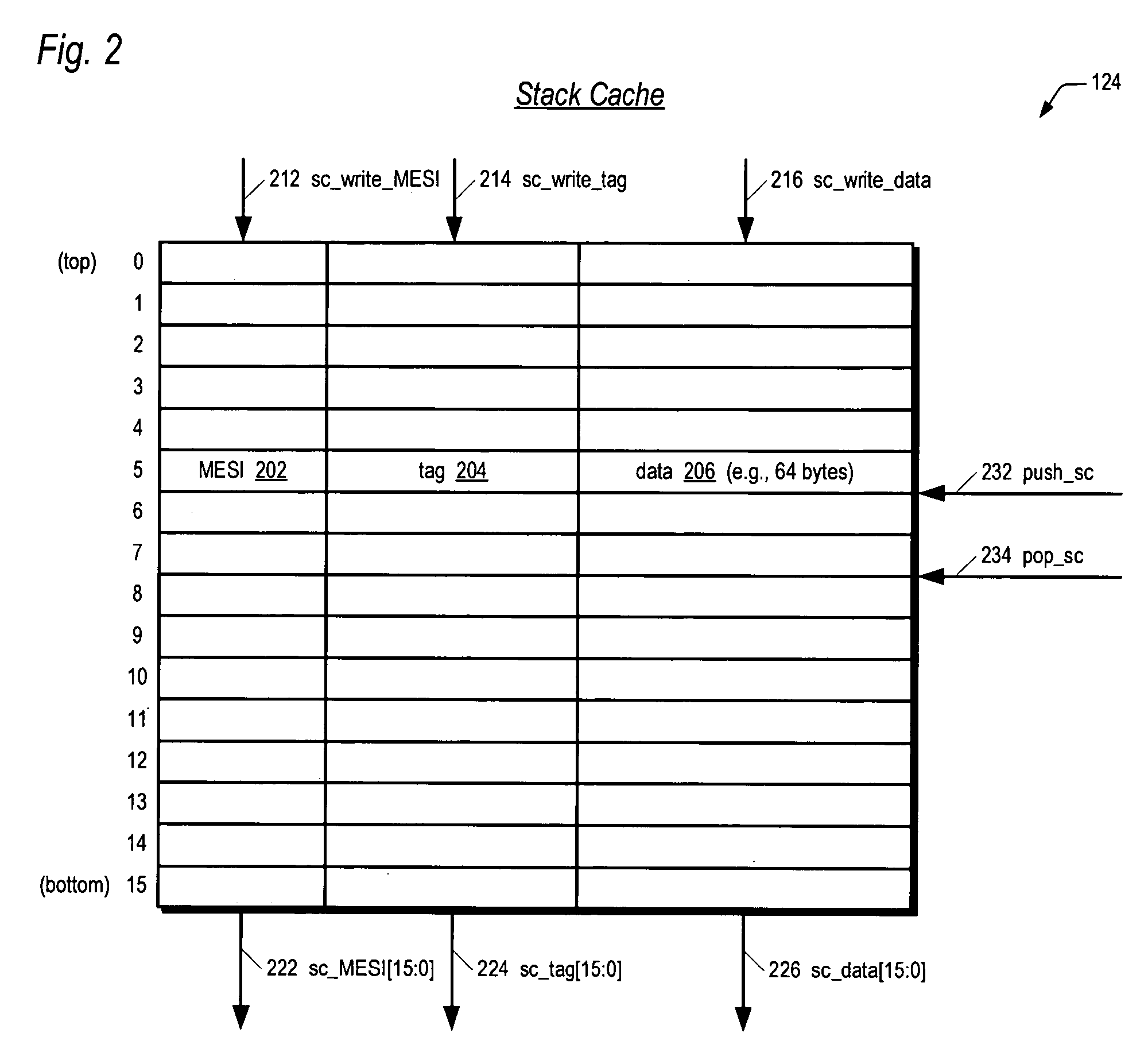
[0250]Although the present invention and its objects, features and advantages have been described in detail, other embodiments are encompassed by the invention. For example, the stack cache or LIFO memory may be embodied in last-in-first-out memory. One example embodiment is a register file functioning as a circular FIFO memory for which top and bottom of stack pointers are maintained in order to determine which entry is to be pushed or popped next and when the stack has been emptied. Furthermore, although embodiments have been described with respect to x86 architecture instructions, in which the stack grows toward decreasing memory addresses, the present invention may be employed in other microprocessors that have stack access instructions in which the stack grows toward increasing memory addresses. In addition, although embodiments of a particular cache line size are disclosed, caches with various line sizes may be employed.

Problems solved by technology

The performance of such a system is hindered by the fact that the time required to read data from the system memory into the microprocessor or to write data from the microprocessor to the system memory is typically much larger than the time required for the microprocessor to execute the instructions that process the data.
However, processor designers recognized long ago that programs tend to access a relatively small proportion of the data a relatively large proportion of the time, such as frequently accessed program variables.
Historically, the size of the cache was typically limited by the amount of physical space on the microprocessor die that could be devoted to the cache.
However, as circuit component geometries steadily decrease, this limitation has also diminished.
But, cache size also affects the access time of a conventional cache.
Unfortunately, a larger cache typically has a longer access time than a smaller cache.
The greater the number of possible locations in which the data may be stored within the cache, the more complicated the circuitry required to locate the data specified by the memory address.
However, there is a constant demand for higher microprocessor clock frequencies, which necessarily implies a reduction in clock cycle times, which implies a larger number of clock cycles to access a cache.

Method used


Image

  • Microprocessor with variable latency stack cache
  • Microprocessor with variable latency stack cache
  • Microprocessor with variable latency stack cache

Examples


Embodiment Construction

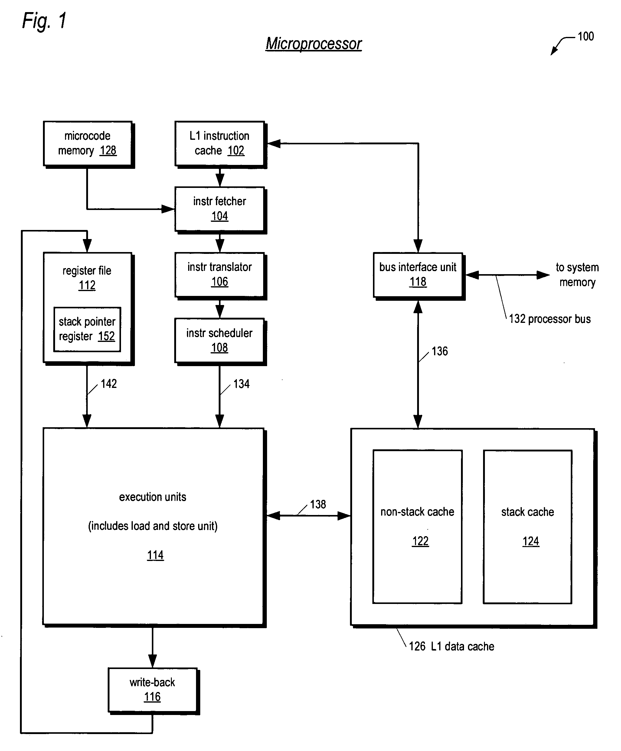
[0037]The present invention takes advantage of the fact that, broadly speaking, programs typically segregate system memory into two regions: a stack region and a non-stack region. The non-stack region is commonly referred to as the heap. A major difference between the stack and the heap is that the heap is accessed in a random access manner; whereas, the stack is generally accessed in a last-in-first-out (LIFO) manner. Another distinction between the stack and the heap is the manner in which the instructions that read or write them specify the address of the location to be read or written. Instructions that read or write the heap generally specify the memory address explicitly. In contrast, instructions that read or write the stack generally specify the memory address implicitly via a special register in the microprocessor, commonly referred to as the stack pointer register. A push instruction updates the stack pointer register by the size of the data to be pushed onto the stack, an...


PUM


Abstract

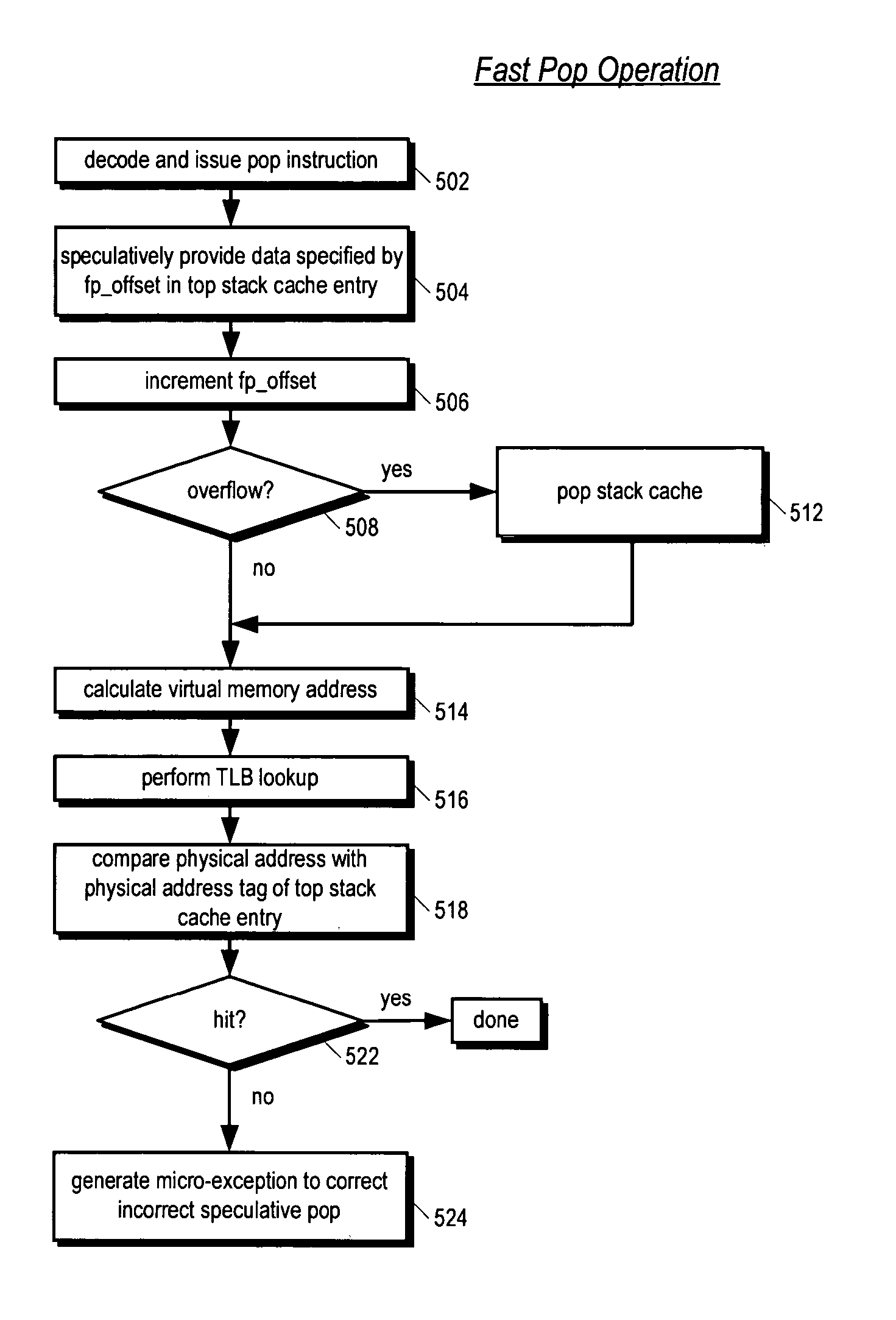
A variable latency cache memory is disclosed. The cache memory includes a plurality of storage elements for storing stack memory data in a first-in-first-out manner. The cache memory distinguishes between pop and load instruction requests and provides pop data faster than load data by speculating that pop data will be in the top cache line of the cache. The cache memory also speculates that stack data requested by load instructions will be in the top one or more cache lines of the cache memory. Consequently, if the source virtual address of a load instruction hits in the top of the cache memory, the data is speculatively provided faster than the case where the data is in a lower cache line or where a full physical address compare is required or where the data must be provided from a non-stack cache memory in the microprocessor, but slower than pop data.

Description

PRIORITY INFORMATION[0001]This application claims priority based on U.S. Provisional Application Ser. No. 60 / 440,767, filed Jan. 16, 2003, entitled FULLY ASSOCIATIVE STACK CACHE.CROSS REFERENCE TO RELATED APPLICATIONS[0002]This application is related to the following co-pending U.S. patent applications, which are filed on the same day as this application, and which have a common assignee and a common inventor.[0003]Ser.DocketNo.NumberTitle10 / 759559CNTR.2057MICROPROCESSOR AND APPARATUSFOR PERFORMING FAST SPECULATIVEPOP OPERATION FROM A STACKMEMORY10 / 759564CNTR.2229MICROPROCESSOR AND APPARATUSFOR PERFORMING SPECULATIVELOAD OPERATIONFROM A STACK MEMORY10 / 759489CNTR.2233MICROPROCESSOR AND APPARATUSFOR PERFORMING FAST POPOPERATION FROM RANDOM ACCESSCACHE MEMORYFIELD OF THE INVENTION[0004]This invention relates in general to the field of cache memories in microprocessors and particularly to cache memories that distinguish between stack and non-stack memory accesses.BACKGROUND OF THE INVEN...

Claims


Application Information

Patent Timeline
IPC IPC(8): G06F12/00G06F9/30G06F9/312G06F9/38G06F12/08G06F12/10
CPCG06F9/3004G06F9/30043G06F9/30134G06F12/1045G06F9/3842G06F12/0875G06F9/383
Inventor HOOKER, RODNEY E.
Owner IP FIRST
Learn More