Press mounted cam

a technology of cams and cams, which is applied in forging presses, manufacturing tools, forging/hammering/pressing machines, etc., can solve the problems of momentari delay of driving engagement, and achieve the effect of less shock on mating components

Active Publication Date: 2007-03-20
ANCHOR LAMINA AMERICA INC
View PDF22 Cites 25 Cited by
  • Summary
  • Abstract
  • Description
  • Claims
  • Application Information

AI Technical Summary

Benefits of technology

[0019]The above objects and other objects which will become apparent upon a reading of the following specification and claims are achieved by suspending the slide on the adapter by structural features establishing a predetermined clearance space which must be taken up before the press can act to cam the slide laterally to be driven along its working angle. This momentarily delays the driving engagement of cam surfaces by the press until some brief time interval after initial contact of the slide with the driver has occurred. This allows the downward momentum of the slide to first be absorbed by the driver before the slide is forcibly cammed along the working angle by the press motion to reduce noise and the peak loading imposed on the slide-driver mating surfaces.
[0020]The slide is preferably suspended on the adapter using one or more T blocks fixed to the slide and captured in corresponding T channel slots at an inboard location on the adapter with a head portion of the T blocks resting on surfaces on each side of the slots. The use of inboard located T blocks eliminates the outboard located retention plates on the sides of the slide previously used.
[0022]In both aerial and die mounted cams, one or more in board locator-guide key projects from the driver and moves into a guide slot in the slide for lateral location and guidance as the slide cam surfaces approaches engagement with the inclined cam surface of the driver. These are much easier to machine laterally locator-guide surfaces. The inboard locator-guide key also eliminates the need for the precision machining of guide surfaces on the ends of the slide.
[0023]Also, in both aerial and die mount cams, a positive retraction mechanism may be incorporated, using a pair of spaced apart T heads affixed to the driver locator-guide key and moving into a mating T channel formed in the slide when engaging the slide through respective spaced apart openings in the T channel and captured as the slide is advanced along the stroke. This effectively doubles the length of mating engagement surfaces on the driver and slide when a positive retraction is necessitated to substantially increase the forces able to be exerted to positively retract the slide.

Problems solved by technology

The presence of this clearance momentarily delays the driving engagement between the adapter and slide mating bearing surfaces until the clearance space is taken up.

Method used


Image

  • Press mounted cam
  • Press mounted cam
  • Press mounted cam

Examples


first embodiment

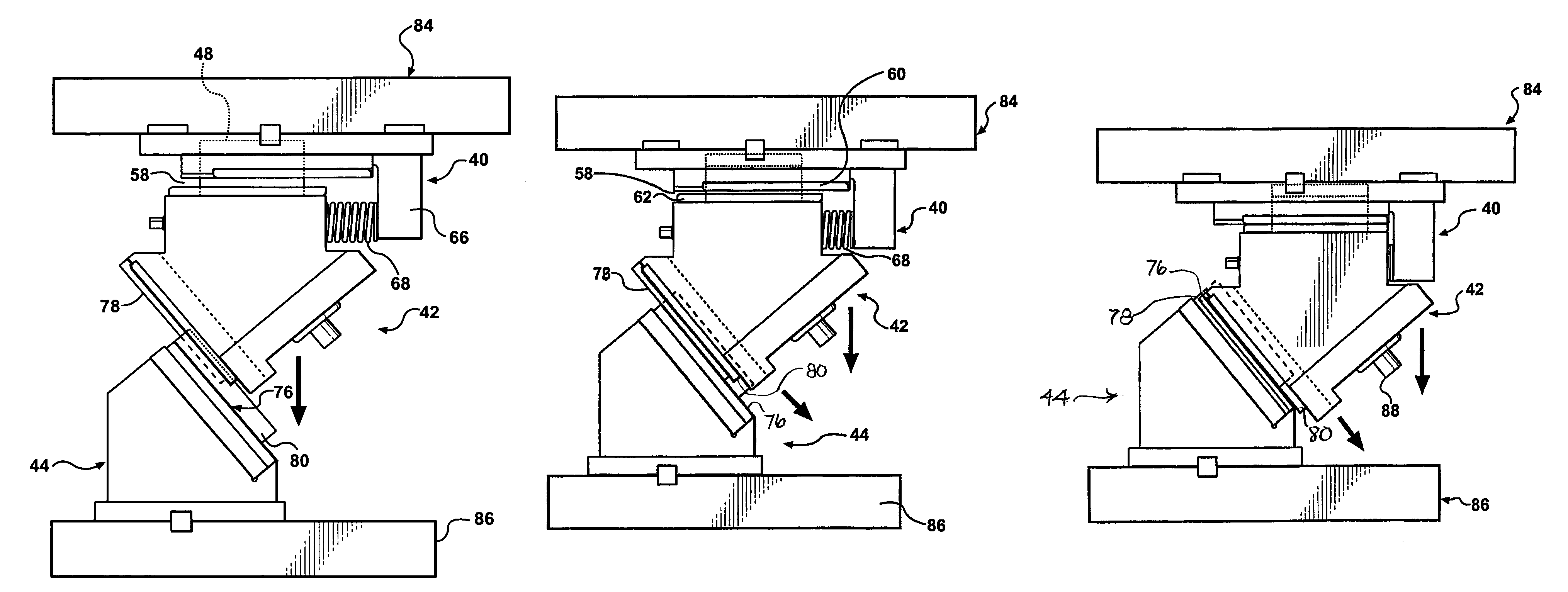
[0066]FIGS. 8A–8D, and 11, illustrate the successive stages of movement of the aerial cam according to the invention.

[0067]In the initial condition shown in FIGS. 8A, the slide 42 is suspended below the adapter 40 by the T blocks 48 and channels 50, with the predetermined clearance space 58 therebetween.

[0068]As the upper platen 84 descends towards the lower platen 86, the locator key 80 enters the slot 82 to provide lateral location and guidance, as seen in FIG. 8B.

[0069]The clearance space 58 is then still present, and the surfaces of the wear plates 76, 78 have not yet engaged.

[0070]Continued descent of the upper platen 84 brings the surfaces of the wear plates 76, 78 into initial contact as seen in FIG. 8C. The clearance space 58 still exists, although now being reduced.

[0071]This initial contact of the wear plates 76, 78 allows the downward momentum of the slide 44 to be absorbed by driver 44 and redirected to cause lateral motion of the slide 42 to be initiated as suggested by...

second embodiment

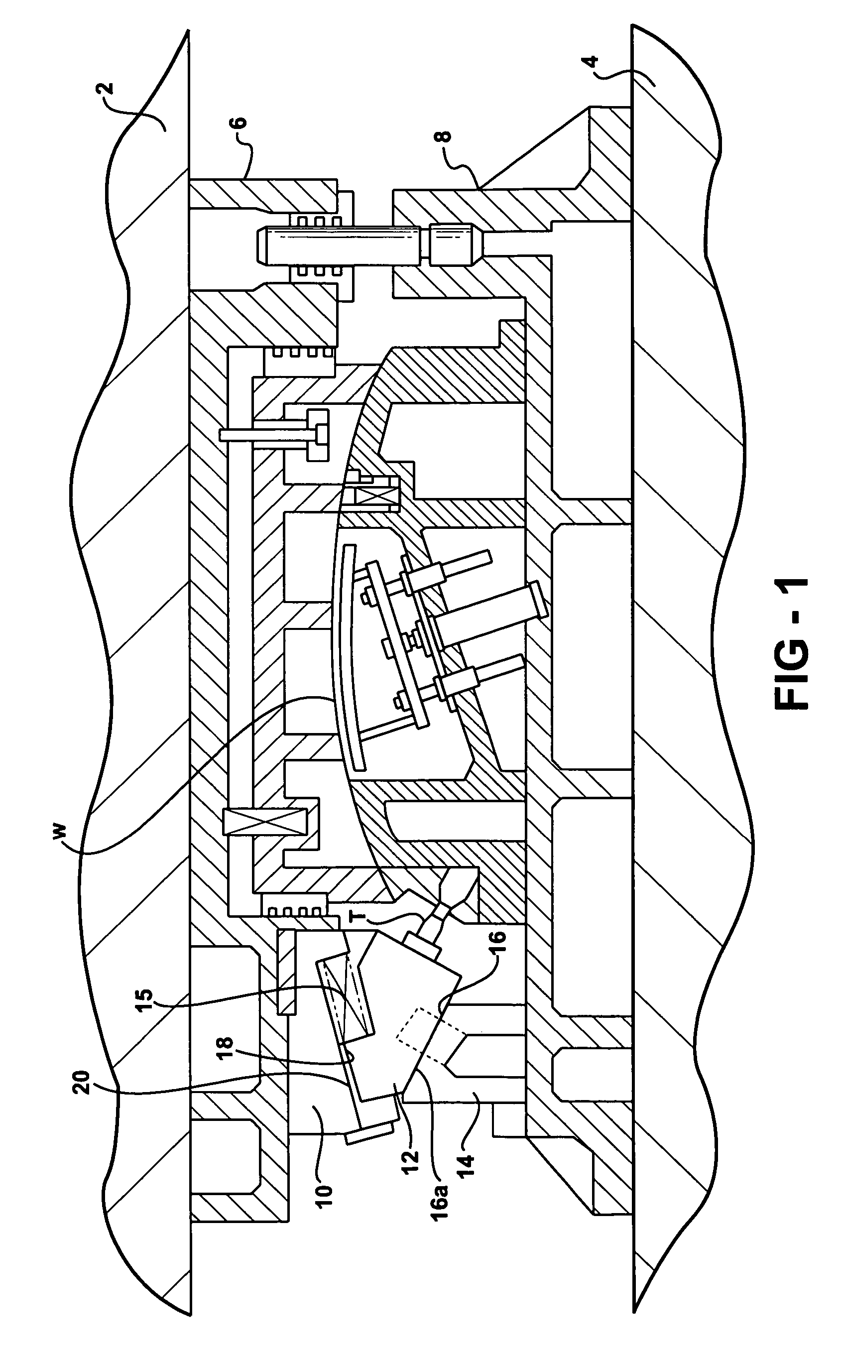
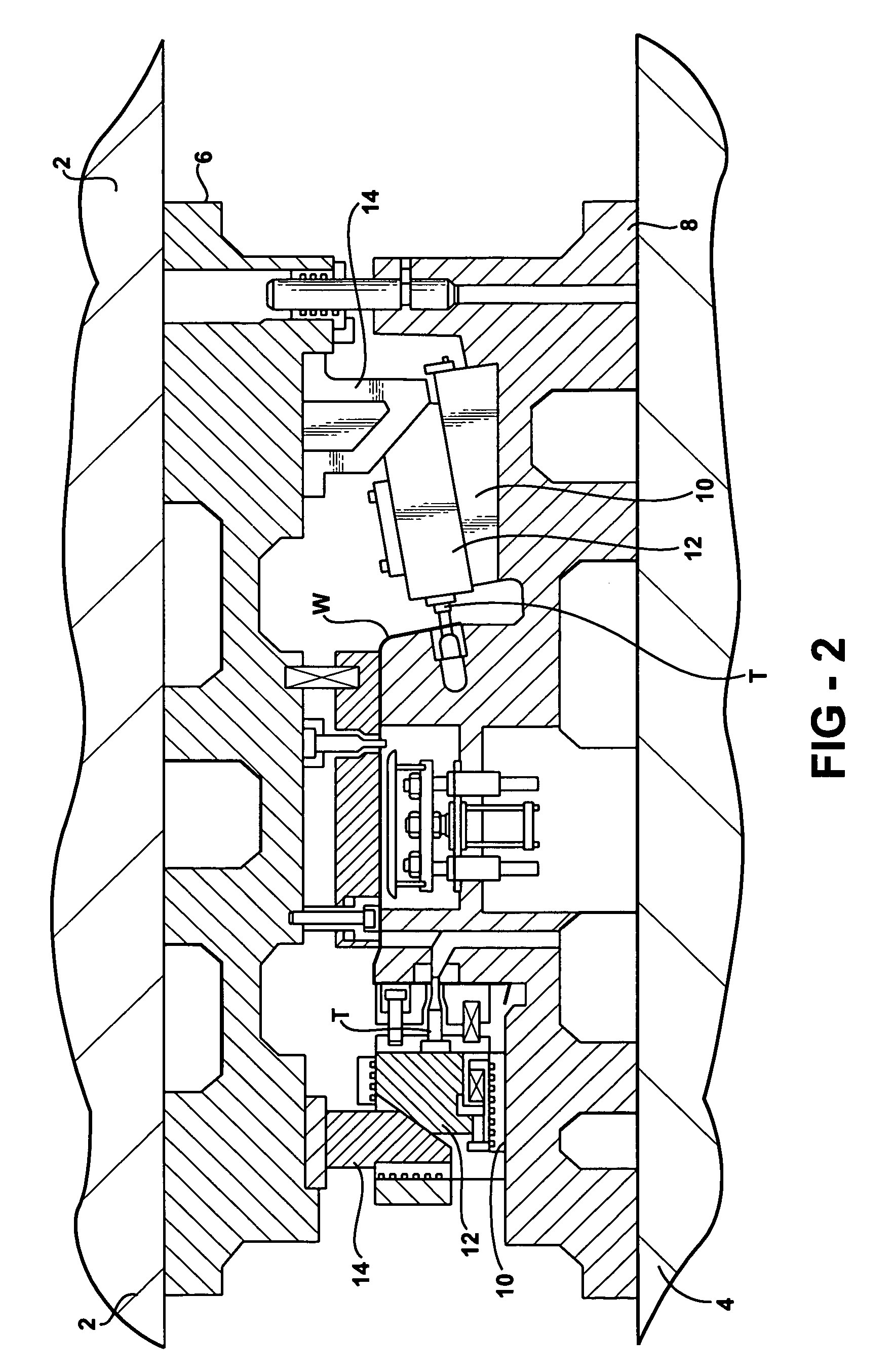
[0077]Referring to FIGS. 13–15 and 16A, 16B, 16C, a simpler aerial cam 100 according to the invention is shown, of a much smaller size.

[0078]In this embodiment, the driver 130 has a horizontal slide surface and the adapter 102 is formed with a sloping cam surface engaging a complementary surface on the slide 106.

[0079]The adapter 102 is mounted on an upper platen 104 (FIGS. 16A–C) of a press. A slide 106 is suspended on the adapter 102 by means of a single centrally located T block 108 secured to an upper sloping surface 110 of a slide block 112 by screws 114.

[0080]A T guide 116 is attached to the adapter body 118 by screws 120, and is formed with a T-shaped channel 125 defined by surfaces 122 and 124 configured to slidably receive the T block 108. The weight of the slide 106 is supported on surfaces 124 by the wings of the T block 108 before the adapter 102 forcibly engages the slide 106 after the slide 106 engages the driver 130 fixed to the lower platen 132 (FIG. 16A). The channe...


PUM

PropertyMeasurementUnit
interfit structureaaaaaaaaaa
momentumaaaaaaaaaa
angleaaaaaaaaaa

Abstract

A press mounted cam has a slide guided on an adapter by structural features including as one or more T blocks fixed to the slide and received in a respective channel formed in the adapter. In an aerial cam embodiment, a vertical clearance space is provided between the T block and adapter channel such that positive driving engagement between cam surfaces on the slide and the adapter is momentarily delayed after the initial engagement of the slide and driver surfaces to let the momentum of the slide be absorbed prior to the beginning of positive driving by the press motion, reducing shock and noise. The slide is laterally located with respect to the driver by an upwardly projecting locator-guide key on the driver received in a central channel in the slide. A positive return is provided by engagement of a driver key having T features received in a T-shaped slide channel and captured therein when the slide is driven laterally. This engagement creates a positive return of the slide when the press upper platen is raised.

Description

CROSS REFERENCE TO RELATED APPLICATION[0001]This application claims the benefit of U.S. provisional Ser. No. 60 / 629,147, filed Nov. 18, 2004.BACKGROUND OF THE INVENTION[0002]This invention concerns press mounted cams, which are mechanisms installed in forming presses to produce a feature on a workpiece being formed within the press by die having an upper part installed on an upper platen of the press and a lower die part installed on a lower press platen. The cam is used to form a punched or tapped hole where the feature is located such that it must be formed by tool motion along a direction at a working angle across the direction of press movement. The press mounted cams are used to produce such crossing tool motion.[0003]These cams are comprised of a “slide”, carrying the tool, a “body” or “adapter” affixed to one of the die parts or press platens on which the slide is slidably mounted, and a separate “driver” mounted on the other of the die parts or press platen. The driver engag...

Claims


Application Information

Patent Timeline
Patent Type & Authority Patents(United States)
IPC IPC(8): B21D5/04B26D5/16
CPCB21D28/32B21J13/04B21J9/18B30B1/06
Inventor CHUN, VICTOR L.RUSSEL, BRIANTAYLOR, BRIAN LEEMADEJ, FRANK
Owner ANCHOR LAMINA AMERICA INC
Why Eureka
Try Eureka