Drive for a motor-driven hand-held tool

a technology of hand-held tools and drives, which is applied in the direction of portable percussive tools, metal sawing apparatuses, bulkheads/piles, etc., can solve the problems of unconsidered unbalance compensation, and achieve the effects of low cost, high stability of support, and convenient mounting

Active Publication Date: 2007-03-20
HILTI AG
View PDF15 Cites 30 Cited by
  • Summary
  • Abstract
  • Description
  • Claims
  • Application Information

AI Technical Summary

Benefits of technology

[0011]Advantageously, the support member is formed of two parts, with the sliding support surface being provided on at least one of the parts. Such a support member, e.g., a support metal sheet can be easily mounted, e.g., after the transmission element has been inserted in a support receptacle of the support.
[0012]Advantageously, the support member is formed as a sheet metal section, which permits to cost-effectively produce the support member. A high stability of the support is insured when the support member is secured to the support with appropriate connection means such as screw means, rivet, and the like.
[0013]According to an advantageous embodiment of the present invention, a support receptacle is provided in the support for receiving a base member of the transmission element. During assembly, the base member can be inserted into receptacle, which generally improves the support of the transmission member.
[0014]It is further advantageous when the upper rim of the base member is flush aligned with the adjacent surface of the support. In this case, the support member can lie on both parts, and a too large backlash of the transmission element is prevent in a mounted condition of the transmission element on the support.

Problems solved by technology

The drawback of a known drive consists in that the unbalance compensation is not contemplated.

Method used


Image

  • Drive for a motor-driven hand-held tool
  • Drive for a motor-driven hand-held tool
  • Drive for a motor-driven hand-held tool

Examples


Embodiment Construction

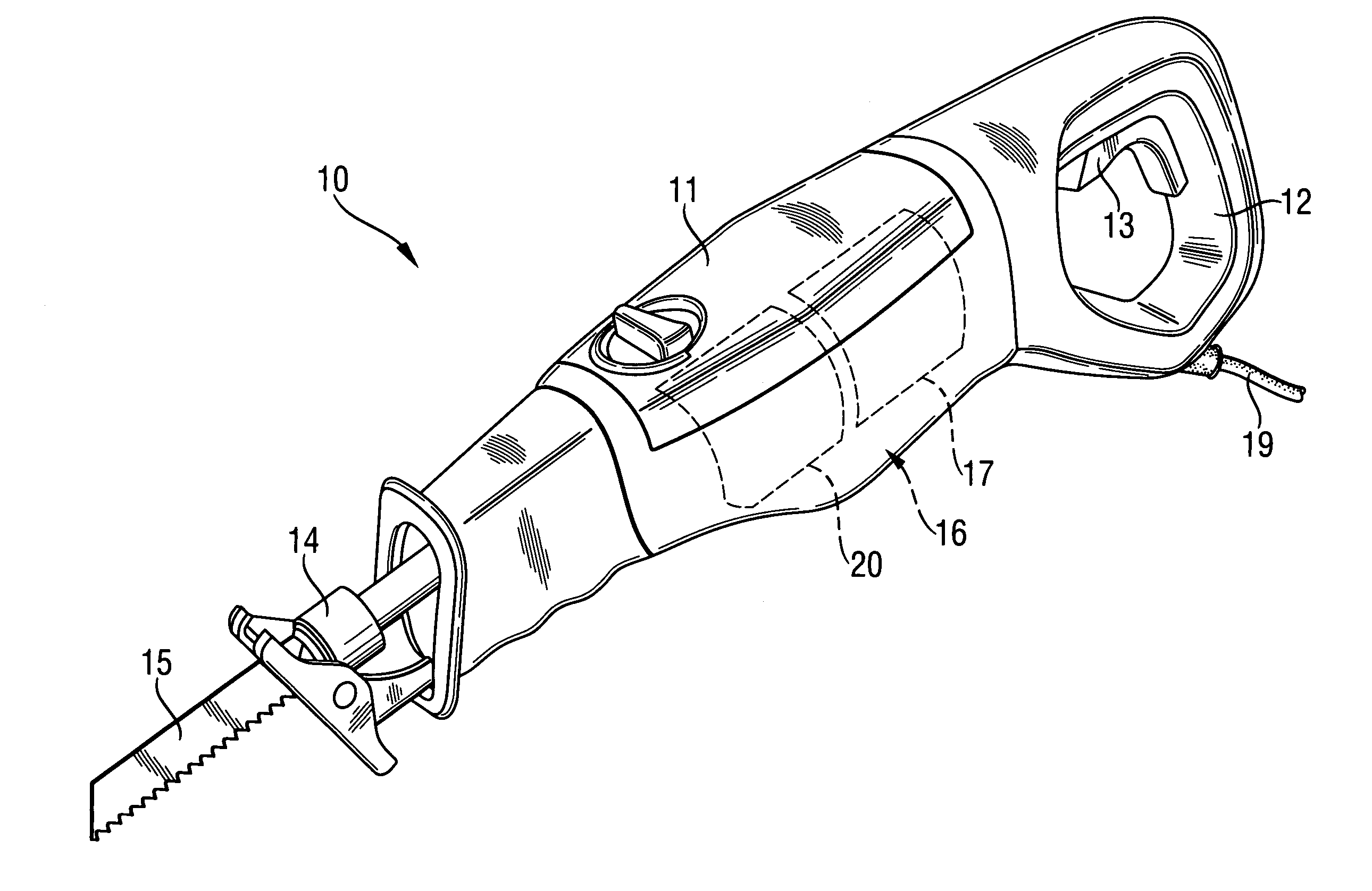
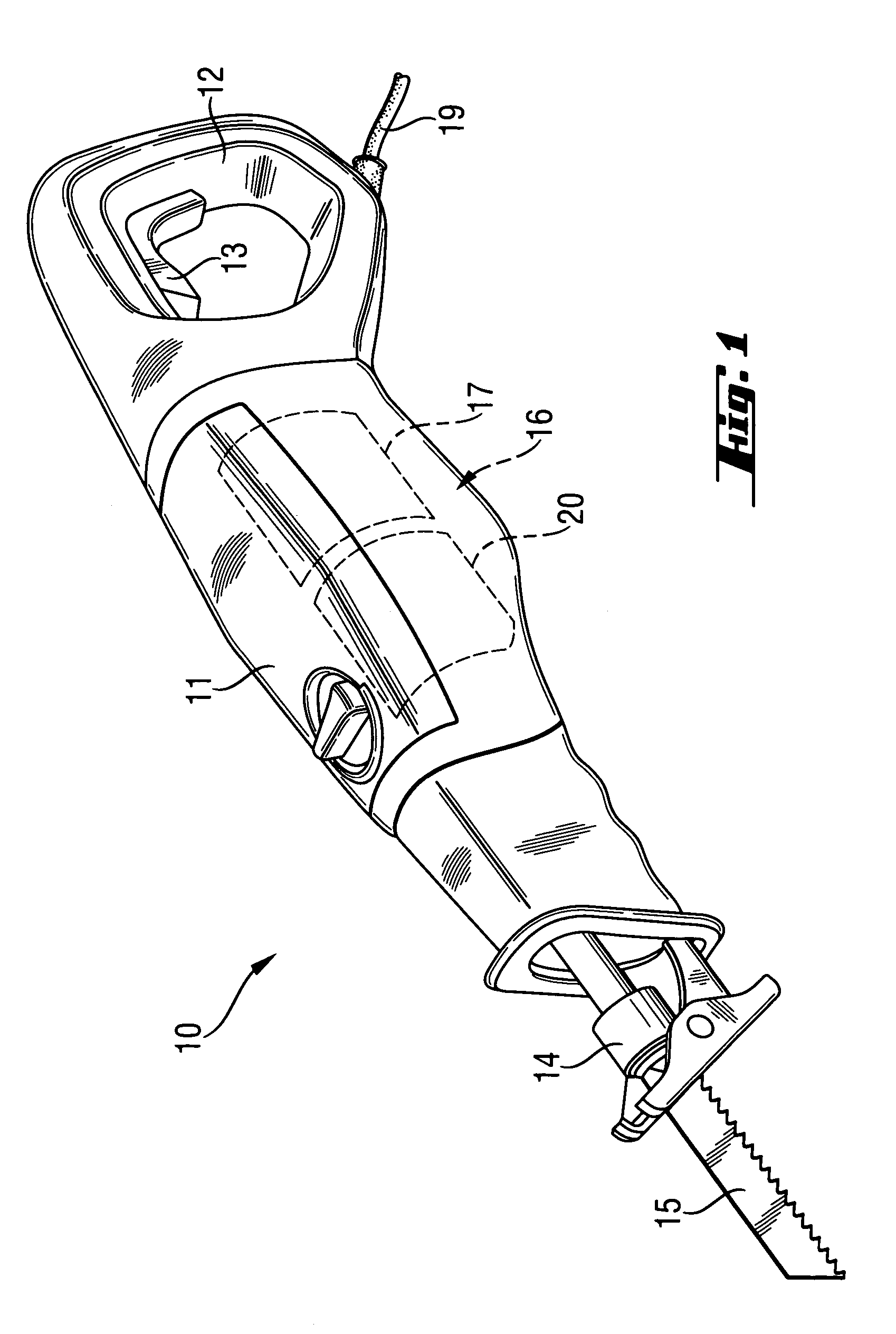
[0021]FIG. 1 shows a motor-driven hand-held tool 10 in form of a saber saw with a drive 16 according to the present invention which is arranged in a multi-part housing 11. The drive 16 includes a motor 17, e.g., an electric motor, and a gear mechanism 20 that converts a rotational movement of the motor 17 in a reciprocating movement. The current supply of the hand-held tool 10 is effected via a network connector 19 in form of a network cable connectable with a power source. Naturally, for current supply, the hand-held tool 10 can be provided with an accumulator, a battery pack, and the like.

[0022]The hand-held tool 10 further has a handle 12 on which an actuation switch 13 is arranged for actuating the hand-held tool 10. At the end of the hand-held 10 opposite the handle 12, there is provided means for securing a working tool in form of a working tool clamp 14 in which a tool 15, e.g., a saw blade is secured. The clamp 14 is secured at a free end of reciprocating drive means 30, suc...


PUM

PropertyMeasurementUnit
reciprocating movementaaaaaaaaaa
massaaaaaaaaaa
stabilityaaaaaaaaaa

Abstract

A drive for a motor-driven hand-held tool includes a motor (17) and a gear mechanism (20) for converting a rotational movement of the motor (17) into a reciprocating movement of the reciprocating drive element (30) for a working tool, with the gear mechanism (20) having a transmission element (23) axially secured on a support (21) with a support member (26) and including a mass-balance member (31), a first eccentric take-off element (24) cooperating with the reciprocating drive element (30) and a second eccentric take-off element (25) cooperating with the mass-balance member (31) for imparting reciprocating movement thereto, and with the support member (26) forming a slide support surface for the mass-balance member (31).

Description

BACKGROUND OF THE INVENTION[0001]1. Field of the Invention[0002]The present invention relates to a drive for a motor-driven hand-held tool having a reciprocating drive element for driving a working tool, with the drive including a motor and a gear mechanism for converting a rotational movement of the motor into a reciprocating movement of the reciprocating drive element and having a transmission element axially secured on a support with a support member and including an eccentric take-off element cooperating with the reciprocating drive element for imparting the reciprocating movement thereto.[0003]2. Description of the Prior Art[0004]Drives of the type described above are used, e.g., in saber or compass saws in which the drive imparts reciprocating movement to a saw blade.[0005]In motor-driven hand-held tools with a reciprocating movement of the working tool, for compensation of unbalance, a balance mass is driven, together with the tool-securing means, and in direction opposite th...

Claims


Application Information

Patent Timeline
Patent Type & Authority Patents(United States)
IPC IPC(8): B25D11/12B23D51/16
CPCB23D51/16
Inventor HAAS, GUENTER
Owner HILTI AG
Why Eureka
Try Eureka