Brake fluid reservoir with improved venting

a technology of brake fluid and reservoir, applied in the field of hydraulic brake systems, can solve problems such as difficulty in escaping brake fluid, and achieve the effect of convenient manufacturing

Inactive Publication Date: 2007-03-20
LUCAS IND PLC
View PDF11 Cites 1 Cited by
  • Summary
  • Abstract
  • Description
  • Claims
  • Application Information

AI Technical Summary

Benefits of technology

[0011]In a modification of the embodiment just described, a rod-shaped extension extends from the underside of the lid directed towards the reservoir interior, through the sealing washer into the reservoir interior. In said form of construction, the sealing washer is annular and also closes off the inlet of the first forced-flow channel towards the reservoir interior. The rod-shaped extension has in its lateral surface at the level of the sealing washer a recess, which connects the inlet of the first forced-flow channel to the reservoir interior. In other words, the recess creates a fluid connection, which leads past the sealing washer radially at the inside, between the reservoir interior and the inlet of the first forced-flow channel. The sealing washer accordingly need not be specially designed to keep the inlet open. Furthermore, the recess in the lateral surface of the rod-shaped extension provides an improved labyrinth effect, which makes it even more difficult for brake fluid to escape from the brake fluid reservoir.

Problems solved by technology

The curvature of the path may be selected differently but always in such a way that makes it difficult for brake fluid to escape.

Method used


Image

  • Brake fluid reservoir with improved venting
  • Brake fluid reservoir with improved venting
  • Brake fluid reservoir with improved venting

Examples


Embodiment Construction

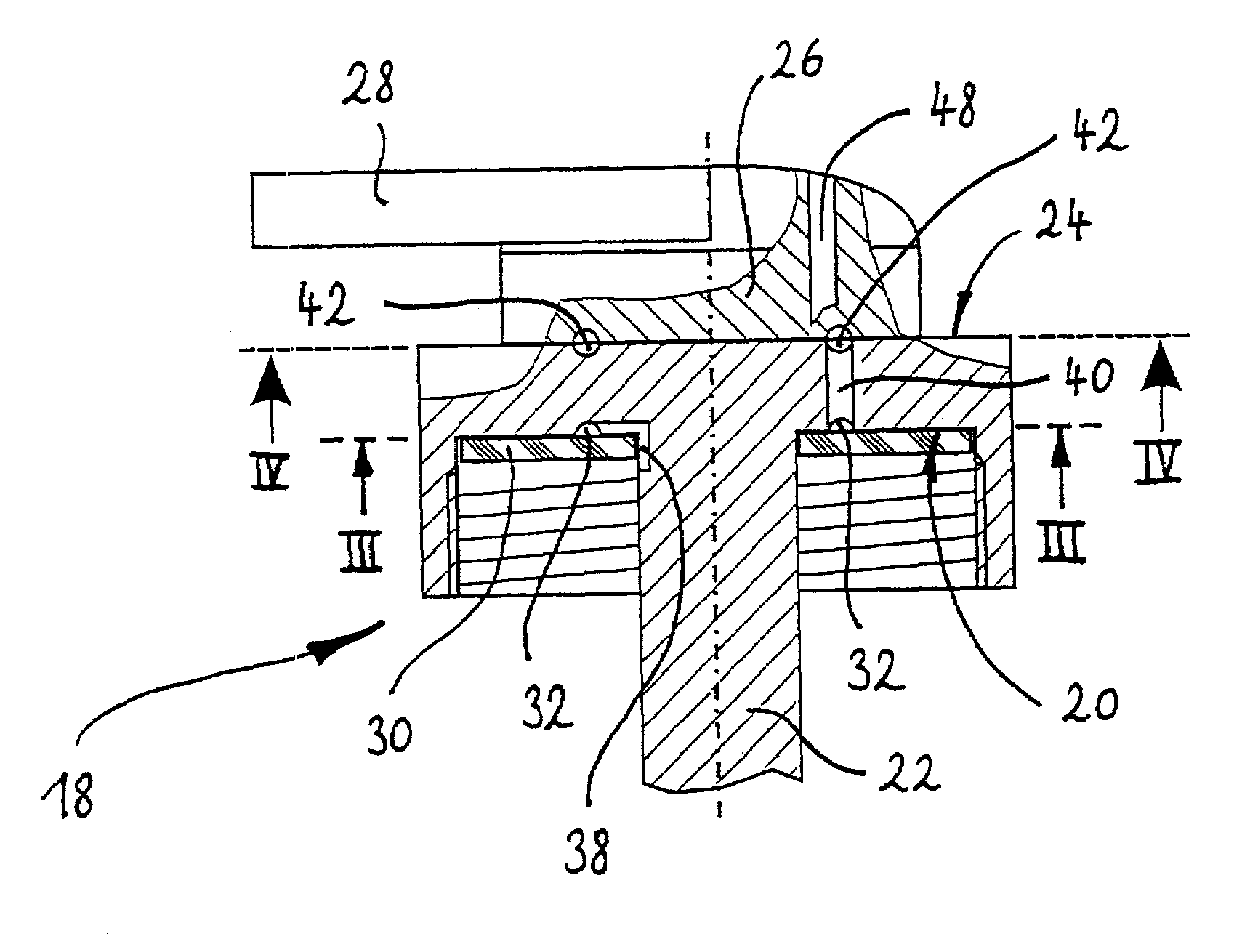
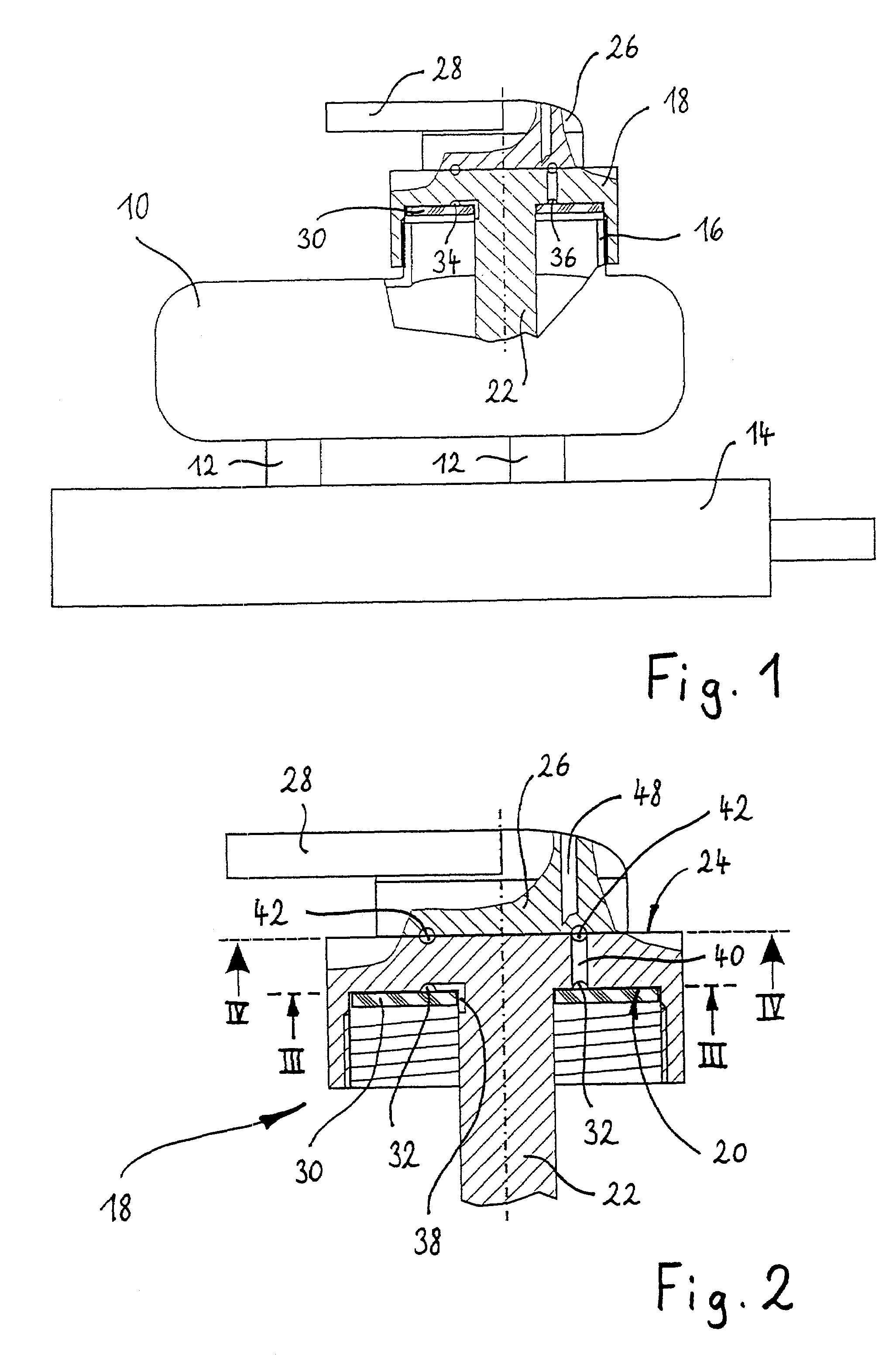
[0022]FIG. 1 shows a brake fluid reservoir 10 of a vehicle hydraulic brake system, which reservoir is connected in a fluid-conducting manner by two couplings 12 extending from its underside to an only diagrammatically reproduced master cylinder 14. As millions of such brake fluid reservoirs are in use, their function is known to experts in the present field and requires no further explanation here.

[0023]The reservoir 10 is made of transparent plastics material and has, formed on its top side, a filler neck 16 having an external thread. Screwed onto the filler neck 16 is a substantially round lid 18, which is provided with an internal thread and closes the opening of the filler neck 16.

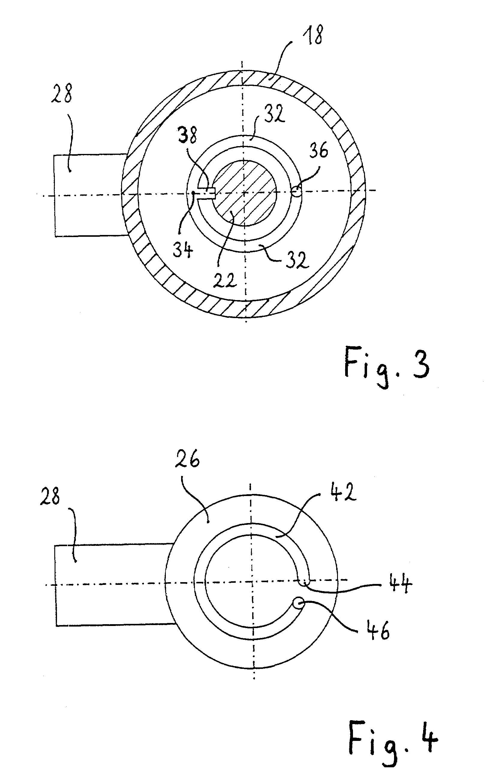
[0024]The lid 18, which is shown in greater detail in FIGS. 2 to 4, is made of plastics material and has an underside 20, from which a rod-shaped extension 22 extends into the reservoir interior. Extending through the extension 22 is a sensor device, which is not illustrated here and which detects the ...


PUM

PropertyMeasurementUnit
angleaaaaaaaaaa
heightaaaaaaaaaa
dimensionaaaaaaaaaa

Abstract

A brake fluid reservoir (10) for a vehicle hydraulic brake system has a filler neck (16), a lid (18) which closes the filler neck, and a device for pressure compensation between the reservoir interior and the ambient atmosphere. In order, when the brake fluid reservoir (10) is in a steeply inclined position, to prevent an escape of brake fluid, in the lid (18) a first brake fluid forced-flow channel (32) is formed, which has an inlet (34) at the inside of the lid and an outlet (36) towards the outside of the lid. The forced-flow channel (32) extends between the inlet (34) and the outlet (36) along a curved path, which in relation to a plan view of the lid (18) runs through at least two quadrants.

Description

CROSS REFERENCE TO RELATED APPLICATIONS[0001]This application is a continuation of International Application No. PCT / EP00 / 09815 filed Oct. 6, 2000, which claims priority to German Patent Application No. 19952336.3 filed Oct. 29, 1999, the disclosures of which are incorporated herein by reference.[0002]The invention relates to a brake fluid reservoir for a vehicle hydraulic brake system. Such a brake fluid reservoir is known from DE 31 22 085 A1.BACKGROUND OF THE INVENTION [0003]Vehicle hydraulic brake systems comprise a brake fluid reservoir, which is usually seated on the master cylinder of the vehicle brake system and connected by means of two couplings in a fluid-conducting manner to the master cylinder. Hydraulic fluid, which is needed to balance the fluid content of the brake system, flows from said brake fluid reservoir into the brake system. Surplus brake fluid moreover flows from the brake system into the brake fluid reservoir. The brake fluid reservoir is accordingly used t...

Claims


Application Information

Patent Timeline
Patent Type & Authority Patents(United States)
IPC IPC(8): B65D51/16B60T11/26B60T11/34B60T11/10B60T17/22
CPCB60T17/225B60T11/26
Inventor LANGE, HANS-CHRISTOPH
Owner LUCAS IND PLC
Why Eureka
Try Eureka