Intervertebral implant

a technology of intervertebral implants and vertebrae, which is applied in the field of artificial biocompatible vertebrae, can solve problems such as severe back pain

Inactive Publication Date: 2007-03-20
DEPUY SYNTHES PROD INC
View PDF153 Cites 187 Cited by
  • Summary
  • Abstract
  • Description
  • Claims
  • Application Information

AI Technical Summary

Problems solved by technology

A number of medical conditions such as compression of spinal cord nerve roots, degenerative disc disease, tumor, and trauma can cause severe back pain.

Method used


Image

  • Intervertebral implant
  • Intervertebral implant
  • Intervertebral implant

Examples


first embodiment

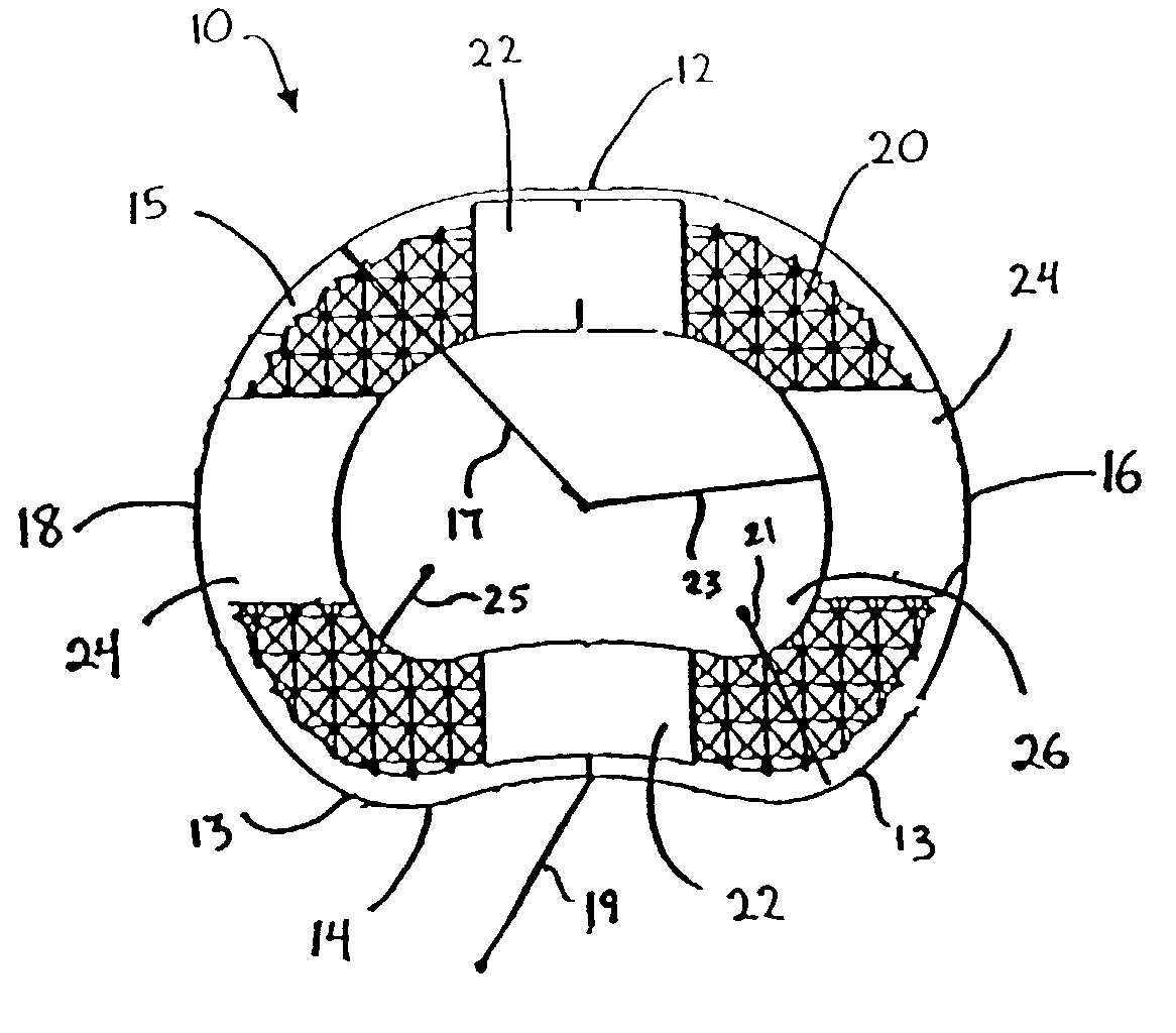
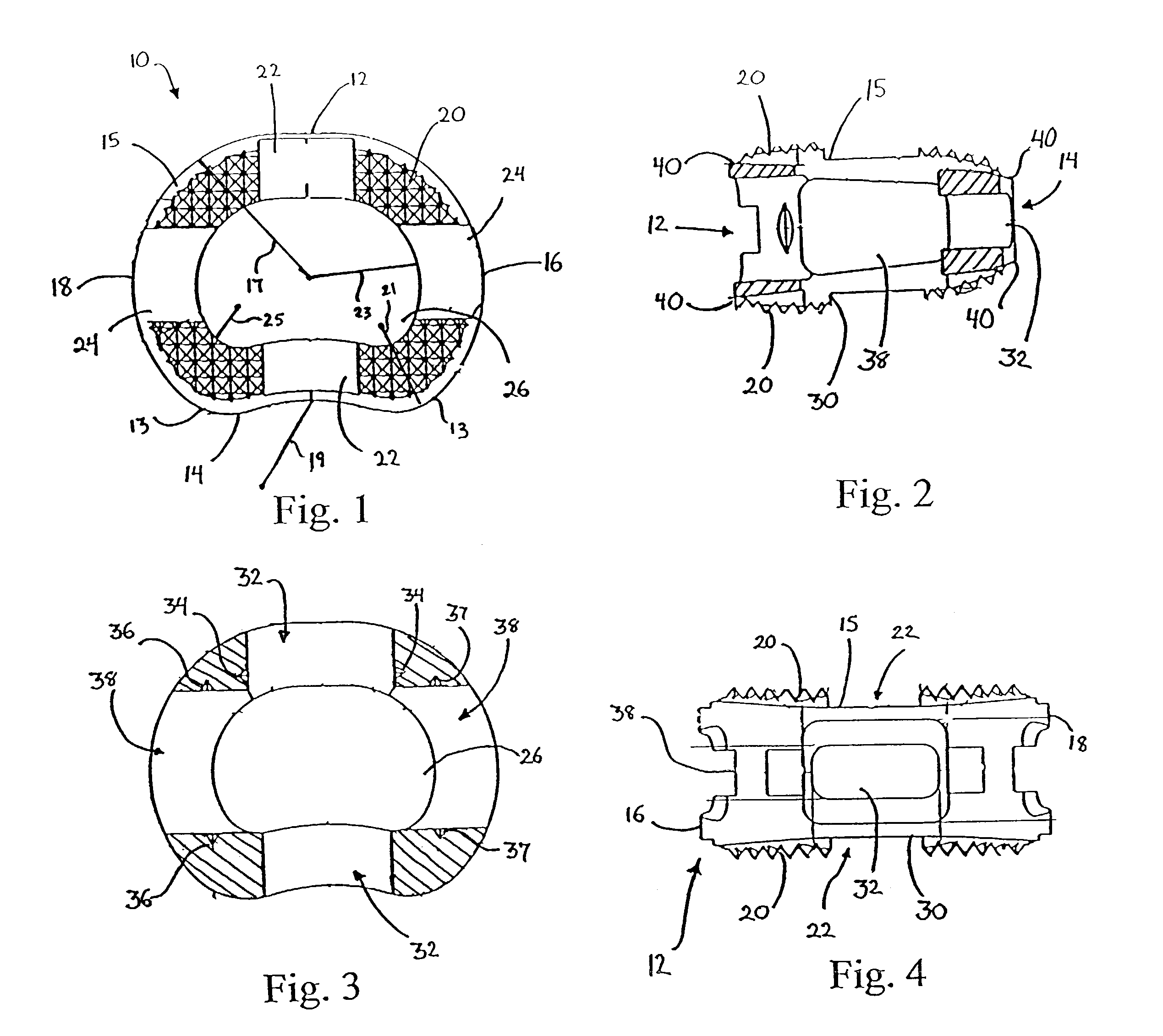
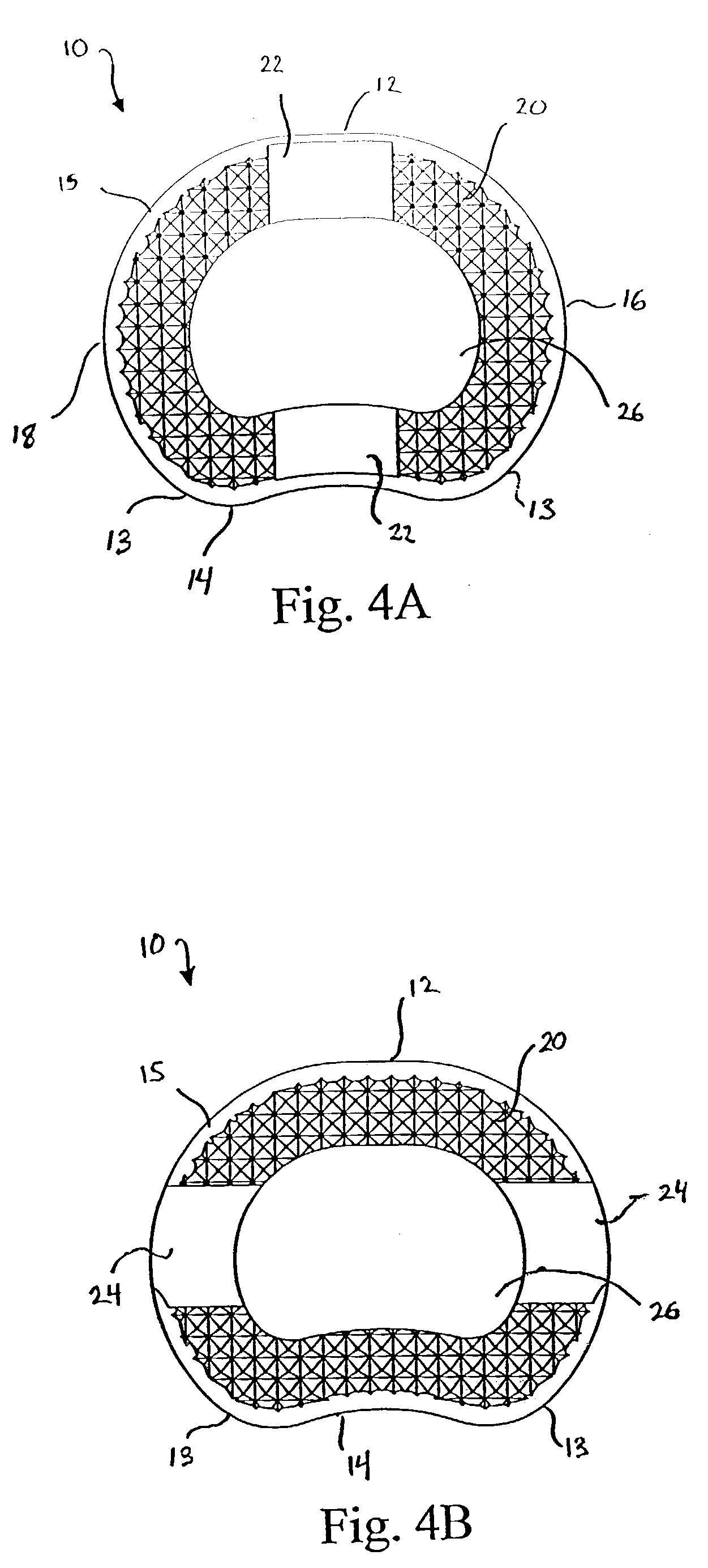
[0085]FIG. 1 shows a top view of intervertebral spacer or implant 10 according to the present invention. Implant 10 has a generally kidney-bean shaped footprint which includes anterior side 12, posterior side 14, and first and second lateral sides 16, 18. Anterior side 12 and lateral sides 16, 18 are all substantially arcuate, preferably convex, in shape while posterior side 14 is substantially arcuate, preferably concave, in shape.

[0086]Implant 10 further includes central bore 26 which can be filled with bone growth inducing substances to allow bony ingrowth and to further assist in the fusion of the adjacent vertebrae and the implant. Central bore 26 has a generally kidney-bean shape that substantially conforms to the kidney-bean shaped footprint of implant 10. The radius of curvature 23 of the arcuate, preferably convex, sides of central bore 26 may be about 6.5 mm to about 8.5 mm, preferably about 7.5 mm, and the radius of curvature 25 of the areas between the preferably convex ...

second embodiment

[0098]FIG. 5 shows a top view of an implant 100. In general, most of the structure of implant 100 is similar or comparable to the structure of implant 10. Accordingly, the equivalent structures of implant 100 have been numbered the same as implant 10 and discussion of the similar components and features is not believed necessary. In this particular embodiment, located on upper surface 15 and lower surface 30 of implant 100, is area 110. Area 110 extends simultaneously in a longitudinal and lateral direction diagonally across implant 110 to facilitate anterio-lateral implant insertion. Although in FIG. 5 area 110 is shown as extending along the entire length of implant 100, area 110 may extend only partially along the length of implant 100.

[0099]Similar to implant 10 discussed above, implant 100 has the two sets of instrument receiving channels to increase surgical flexibility when inserting implant 100 and to facilitate the insertion process by creating more surgical insertion alter...

third embodiment

[0100]FIG. 9 shows a top view of an implant 200. In general, most of the structure of implant 200 is similar or comparable to the structure of implant 10. Accordingly, the equivalent structures of implant 200 have been numbered the same as implant 10 and discussion of the similar components and features is not believed necessary. In this particular embodiment, instead of having instrument receiving channels, implant 200 has threaded bores 210, 212. Threaded bores 210, 212 are sized to receive an implantation instrument such as a threaded inserter.

[0101]As can best be seen in FIGS. 10 and 11, threaded bore 210 is located on lateral side 18. This location allows for insertion of implant 200 in a lateral fashion. Although, threaded bore 210 is located on lateral side 18, it may also be located on lateral side 16. This location also allows for insertion of implant 200 in a lateral direction. FIGS. 11 and 12 show threaded bore 212 which is located on anterior side 12 of implant 200. This...


PUM

PropertyMeasurementUnit
lengthaaaaaaaaaa
lengthaaaaaaaaaa
lengthaaaaaaaaaa

Abstract

A vertebral implant for fusing adjacent vertebrae or for replacing vertebral bodies is disclosed. The implant is a biocompatible metal, resorbable, or radiolucent implant conforming substantially in size and shape with an end plate of a vertebra. The implant preferably has a wedge-shaped profile to restore disc height and the natural curvature of the spine. The top and bottom surfaces of the implant have areas with a plurality of teeth to resist expulsion and provide initial stability and areas devoid of any protrusions to receive implantation instrumentation. The implant also has a stackability feature. The implant provides initial stability needed for fusion without stress shielding.

Description

FIELD OF THE INVENTION[0001]This invention relates to an artificial biocompatible vertebral device and, more particularly, to an intervertebral spinal implant for use in the treatment of back pain.BACKGROUND OF THE INVENTION[0002]A number of medical conditions such as compression of spinal cord nerve roots, degenerative disc disease, tumor, and trauma can cause severe back pain. Intervertebral fusion is one surgical method of alleviating back pain. In intervertebral fusion, two adjacent vertebral bodies are fused together by removing the affected intervertebral disc and inserting an implant that would allow for bone to grow between the two vertebral bodies to bridge the gap left by the disc removal. Another surgical method of relieving back pain is by corpectomy. In corpectomy, a diseased or damaged vertebral body along with the adjoining intervertebral discs are removed and replaced by a spinal implant that would allow for bone to grow between the closest two vertebral bodies to br...

Claims


Application Information

Patent Timeline
Patent Type & Authority Patents(United States)
IPC IPC(8): A61F2/44A61F2/00A61F2/02A61F2/28A61F2/30A61F2/46
CPCA61F2/442A61F2/44A61F2/4465A61F2/28A61F2/4611A61F2002/30062A61F2002/3008A61F2002/30133A61F2002/3023A61F2002/30331A61F2002/30433A61F2002/30599A61F2002/30604A61F2002/30772A61F2002/30841A61F2002/4475A61F2002/4629A61F2210/0004A61F2220/0033A61F2220/0041A61F2230/0015A61F2230/0069A61F2250/0063A61F2250/0098A61F2310/00023A61F2/30744A61F2002/30593A61F2002/30843
Inventor RHODA, WILLIAM S.
Owner DEPUY SYNTHES PROD INC
Why Eureka
Try Eureka