Gas turbine engine rotor balancing

a technology of rotors and gas turbine engines, applied in the direction of propellers, propulsive elements, water-acting propulsive elements, etc., can solve the problems of uncontrollable material removal process and creation of further stress concentration zones, and achieve the effect of reducing weigh

Active Publication Date: 2013-08-15
PRATT & WHITNEY CANADA CORP
View PDF1 Cites 22 Cited by
  • Summary
  • Abstract
  • Description
  • Claims
  • Application Information

AI Technical Summary

Benefits of technology

[0004]In one aspect, there is provided a method of balancing a gas turbine engine rotor, the method comprising: a) obtaining a rotor disc with a circumferential array of tabs projecting from a peripheral rim of the disc and with stress shielding scallops between the tabs, the ta

Problems solved by technology

However, the final manual material removal process is not controlled as well as milling and may possibly result in the creation of further str

Method used


Image

  • Gas turbine engine rotor balancing
  • Gas turbine engine rotor balancing
  • Gas turbine engine rotor balancing

Examples


Embodiment Construction

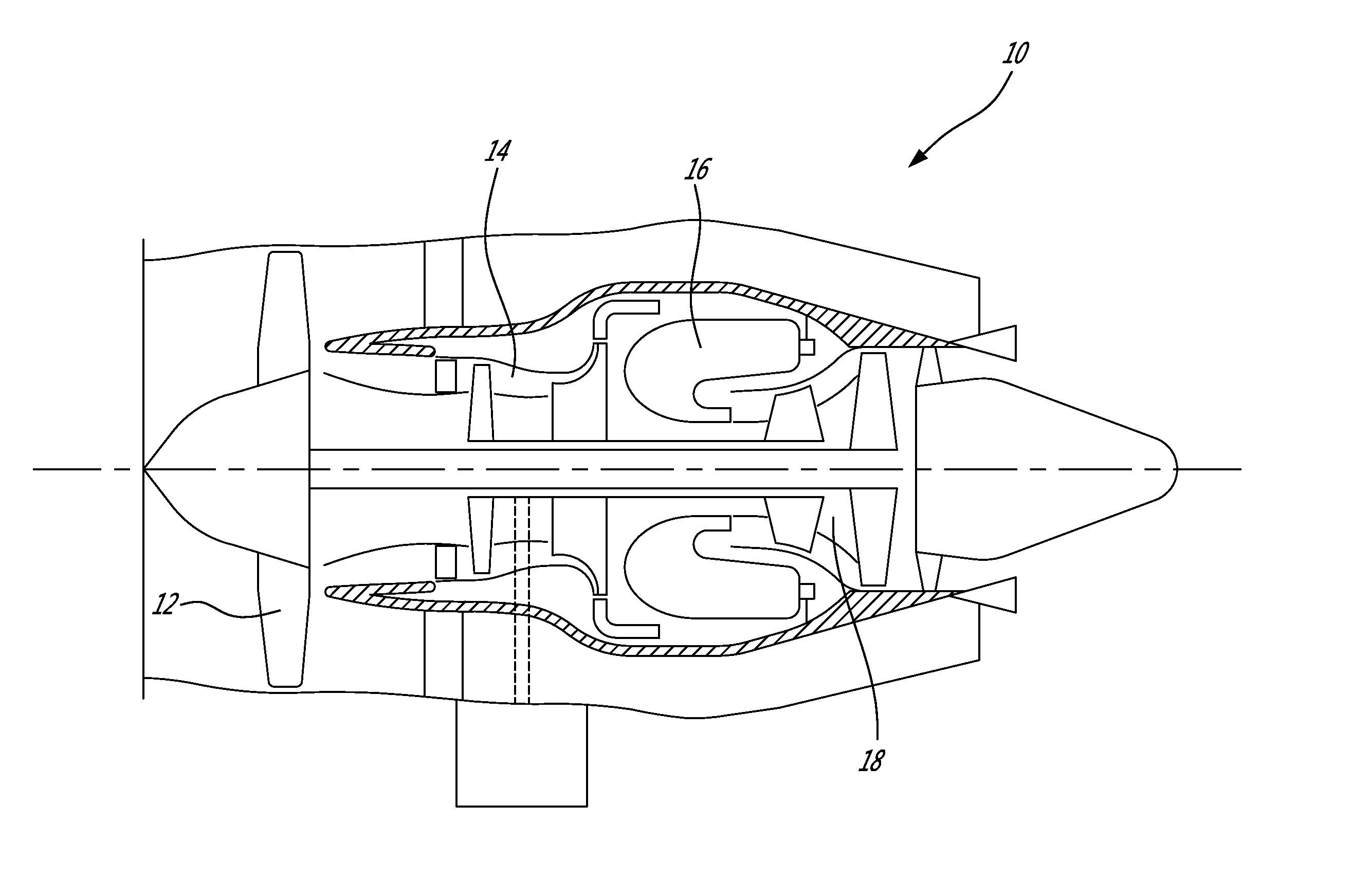
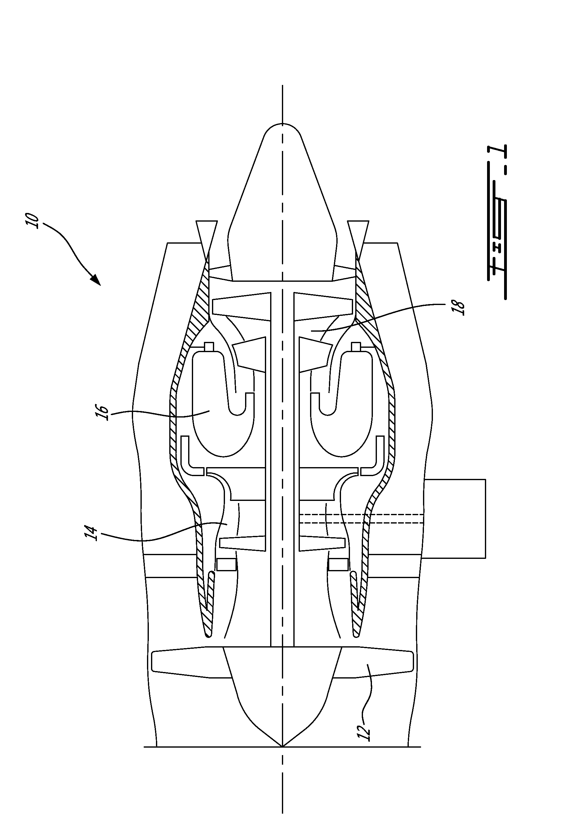
[0013]FIG. 1 illustrates a turbofan gas turbine engine 10 of a type preferably provided for use in subsonic flight, generally comprising in serial flow communication a fan 12 through which ambient air is propelled, a multistage compressor 14 for pressurizing the air, a combustor 16 in which the compressed air is mixed with fuel and ignited for generating an annular stream of hot combustion gases, and a turbine section 18 for extracting energy from the combustion gases.

[0014]The fan 12, the compressor 14 and the turbine 18 each have rotary components, which need to be balanced. The rotary components may, for instance, be provided in the form of an integrally bladed rotor commonly referred to as an IBR or a Blisk, or in the form of a bladed rotor assembly comprising a set of individual blades detachably mounted in slots defined in a rim of the rotor disc. While the present balancing method will be hereinafter described in connection with an integrally bladed fan rotor, it is understoo...


PUM

PropertyMeasurementUnit
Stress optical coefficientaaaaaaaaaa

Abstract

A method of balancing a gas turbine engine rotor comprises the step of obtaining a rotor disc with a circumferential array of balance tabs projecting from a peripheral rim of the disc. Stress shielding scallops are defined in the rotor disc between the tabs. The balancing is achieved by removing material from at least one of the tabs.

Description

TECHNICAL FIELD[0001]The application relates generally to gas turbine engines and, more particularly, to balancing of rotors.BACKGROUND OF THE ART[0002]Gas turbine engine rotors, such as fan, compressor and turbine rotors, can be balanced by removal of material. The material removal process usually involves milling at least one groove or notch into a surface of the rotor, checking the unbalance and then further removing a small amount of material from the notch(es) (typically with a hand held tool) to perfect the balance. These notches may create high stress areas in the rotor. Typically a minimum radius is required at the ends of the balancing notches to keep stresses to an acceptable level. However, the final manual material removal process is not controlled as well as milling and may possibly result in the creation of further stress concentration zones in the form of small undulations at the surface of the notches or in the form of an undercut at the ends of the radius. To contro...

Claims


Application Information

Patent Timeline
IPC IPC(8): B64C11/06B23P15/02
CPCF01D5/027Y10T29/49336B23P15/02F05D2230/10F16F15/32F05D2220/32F05D2260/15
Inventor STONE, PAUL
Owner PRATT & WHITNEY CANADA CORP
Why Eureka
Try Eureka