Electronic optical lens barrel and production method therefor

a production method and technology for electron beams, applied in the direction of beam deviation/focusing by electric/magnetic means, instruments, therapy, etc., can solve the problems of bulky and expensive equipment, adversely affecting the focus accuracy of electron beams, and electrostatic charge tends to build up, so as to achieve high resistance electrical conductivity

Inactive Publication Date: 2007-03-20
TOUDAITLO LTD
View PDF11 Cites 7 Cited by
  • Summary
  • Abstract
  • Description
  • Claims
  • Application Information

AI Technical Summary

Problems solved by technology

However, this engenders problems in terms of bulky and expensive equipment.
Furthermore, high velocity electrons engender the following problems:(a) Because the electron beam penetrates the surface of the sample, it is no longer suitable for observing the surface.(b) There will be deleterious effects, such as the sample being destroyed by the electron beam.(c) With biological samples, the material is nonconductive, and thus electrostatic charge tends to build up.
Charged material has an impact on the electric field, adversely affecting the precision of the focus of the electron beam.
Unfortunately, the electrostatic lenses used in electron optical lens columns require high precision in their placement and dimensions.
When lens columns have been made smaller, there has been a tendency for there to be increased error in the positioning and dimensions of the electrostatic lenses, which may lead to reductions in focusing precision.

Method used


Image

  • Electronic optical lens barrel and production method therefor
  • Electronic optical lens barrel and production method therefor
  • Electronic optical lens barrel and production method therefor

Examples


Embodiment Construction

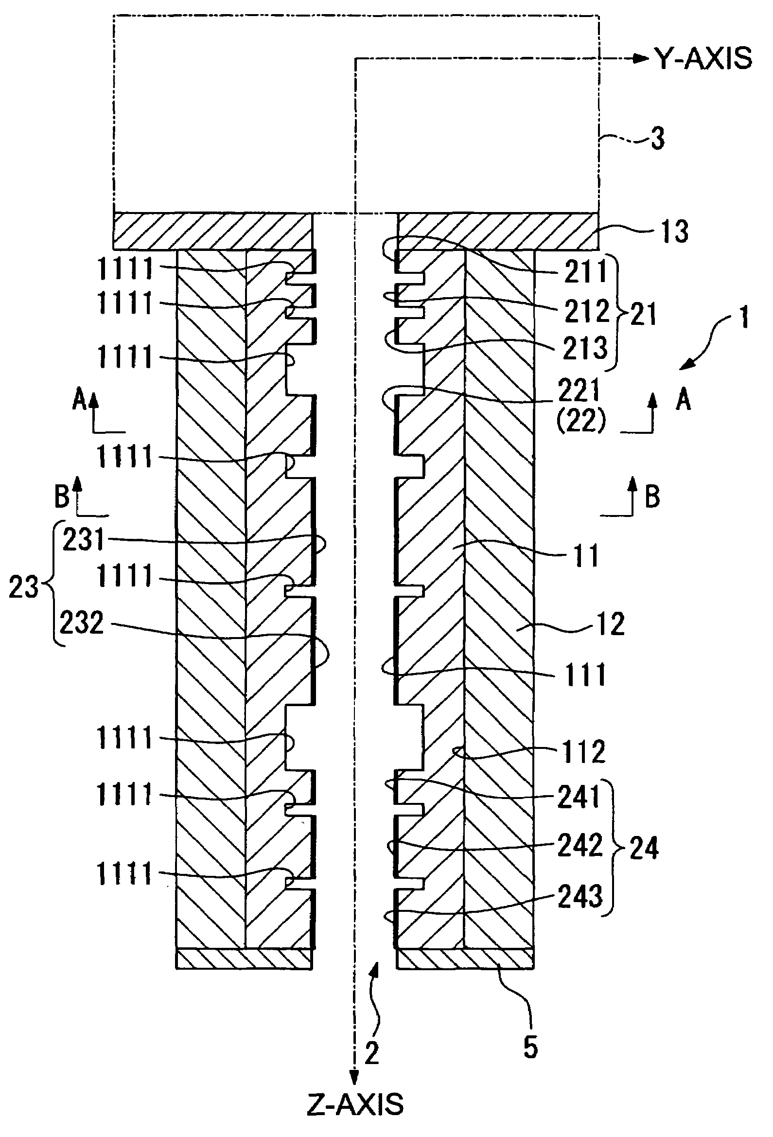
[0065]An electron optical lens column according to a first example of the present invention will be explained below, based on FIGS. 1 through 12. The lens column according to this example embodiment is provided with a column unit 1, an electrostatic lens (sometimes abbreviated as simply “lens” in this description) 2, disposed on the inner surface of this column unit 1, an electron gun chamber 3, interconnections 4, and a secondary electron detector 5. (See FIGS. 1 through 7.)

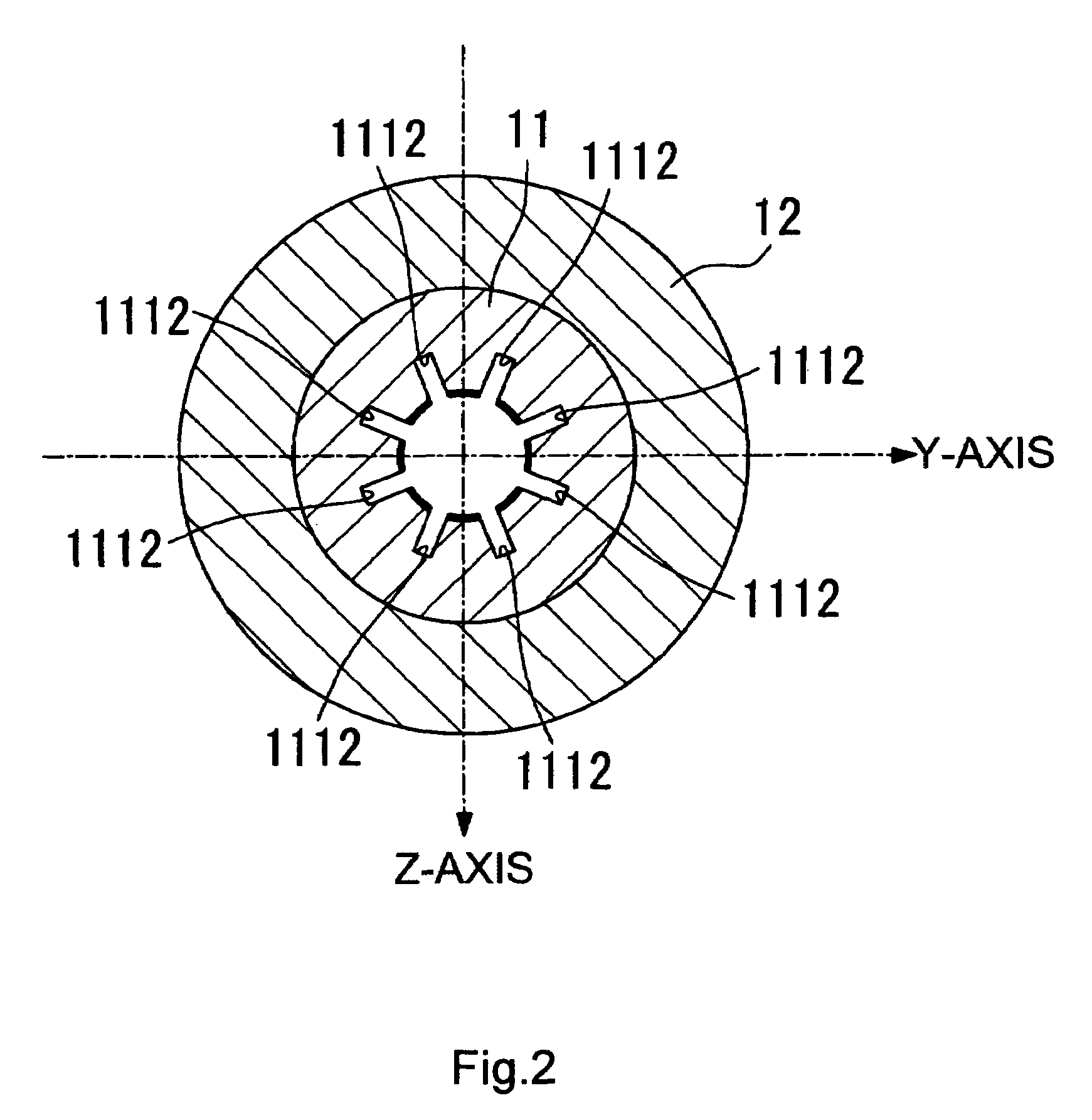
[0066]The column unit 1 is equipped with an inner column 11, and outer column 12, and a flange 13. (See FIG. 1.) A high-resistance electrically conductive ceramic is used as the material for all of these in this example embodiment. Furthermore, in this example embodiment, the resistivity of the high-resistance electrically conductive ceramic is in the range of 108 to 1010 Ω-cm. More preferably, the resistivity should be in the range of about 108 to 109 Ω-cm. Resistivities that are too high will prevent the elect...


PUM


Abstract

The present invention provides an electron optical lens column suitable for miniaturization, and provides the manufacturing method thereof. The column unit (1) comprises an inner column (11) and an outer column (12). The column unit is, as a whole, structured from a high-resistance electrically conductive ceramic. Electrostatic lenses (21, 22, 23, and 24) are affixed to the inner surface (111) of the inner column using a means such as plating or vapor deposition. Of the electrodes or electrode parts (211–213, 221, 231, 232, and 241–243) from which the lens is structured, those that share the same electric potential are connected by shared interconnections. This makes it possible to connect all of the electrodes or electrode parts with shared electric potentials as a group to the external interconnections.

Description

TECHNICAL FIELD[0001]The present invention relates to electron optical lens columns and to manufacturing methods thereof.BACKGROUND OF THE INVENTION[0002]Electron optical lens columns are used in order to produce lens effects on electron beams such as in scanning electron microscopes (SEMs) and ion beam (EB) equipment. An example of a lens column used in an SEM is described as an “electrostatic lens” in Japanese Unexamined Patent Application Publication H 6-187901.[0003]However, recently there have been demands for high precision and tighter focusing of electron beams for the purposes of, for example, microlithography processes. Increasing the degree of focus requires high acceleration of the electrons through applying a high voltage. However, this engenders problems in terms of bulky and expensive equipment. Furthermore, high velocity electrons engender the following problems:[0004](a) Because the electron beam penetrates the surface of the sample, it is no longer suitable for obse...

Claims


Application Information

Patent Timeline
Patent Type & Authority Patents(United States)
IPC IPC(8): H01J3/26G21K1/08H01J3/14H01J37/12H01J37/147H01J37/153H01J37/16
CPCH01J37/12H01J37/153H01J37/147H01J2237/1215H01J37/16
Inventor OKUMURA, KATSUYAMIYOSHI, MOTOSUKE
Owner TOUDAITLO LTD
Why Eureka
Try Eureka