
Cable antenna assembly having slots in grounding sleeve

a technology of grounding sleeves and antenna assemblies, which is applied in the direction of resonant antennas, elongated active elements, collapsable antennas, etc., can solve the problems of inability to tune the grounding portion, the fixing position of coaxial cables, and the inability to crimp or solder the quality of the crimp or soldering to affect the receiving/transmitting effect of the cable antenna assembly, etc., to achieve the effect of easy assembly of cable antenna

Inactive Publication Date: 2007-03-20
HON HAI PRECISION IND CO LTD
View PDF13 Cites 7 Cited by
  • Summary
  • Abstract
  • Description
  • Claims
  • Application Information

AI Technical Summary

Benefits of technology

The present invention provides a cable antenna assembly with a grounding sleeve that makes it easy to assemble a cable antenna element. The assembly includes a connecting portion, a rotating portion, and a cable antenna element. The grounding sleeve is inserted between an inner ring and an outer ring in the rotating portion and has a fixing hole for connecting with the outer conductor of the cable antenna element and a slot for securely fixing the cable antenna element. The technical effect of this invention is to provide a simple and efficient way to connect a cable antenna element to an electronic device.

Problems solved by technology

Since the information appliances usually have a small size, a conventional antenna occupying a great amount of space is not suitable for such an application.
Additionally, the quality of crimping or soldering affects receiving / transmitting effect of the cable antenna assembly.
Furthermore, once crimping or soldering step is done, the fixing position of the coaxial cable and the grounding portion cannot be tuned, so as not to achieve a better receiving / transmitting effect of the cable antenna assembly by tuning the fixing position thereof.

Method used


Image

  • Cable antenna assembly having slots in grounding sleeve
  • Cable antenna assembly having slots in grounding sleeve
  • Cable antenna assembly having slots in grounding sleeve

Examples


Embodiment Construction

[0015]Reference will now be made in detail to preferred embodiments of the present invention.

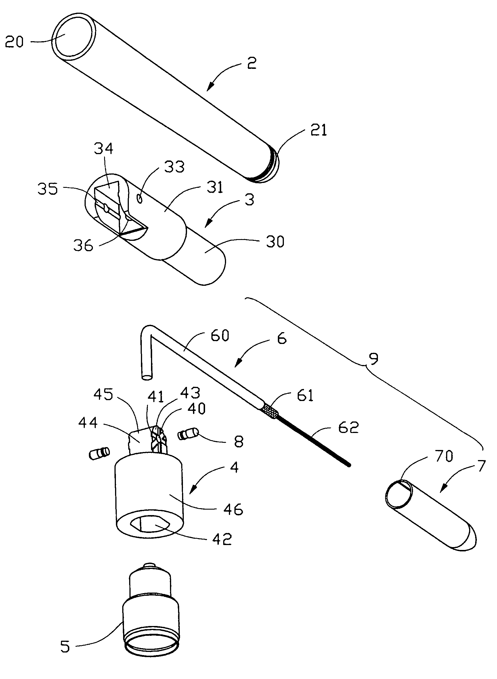
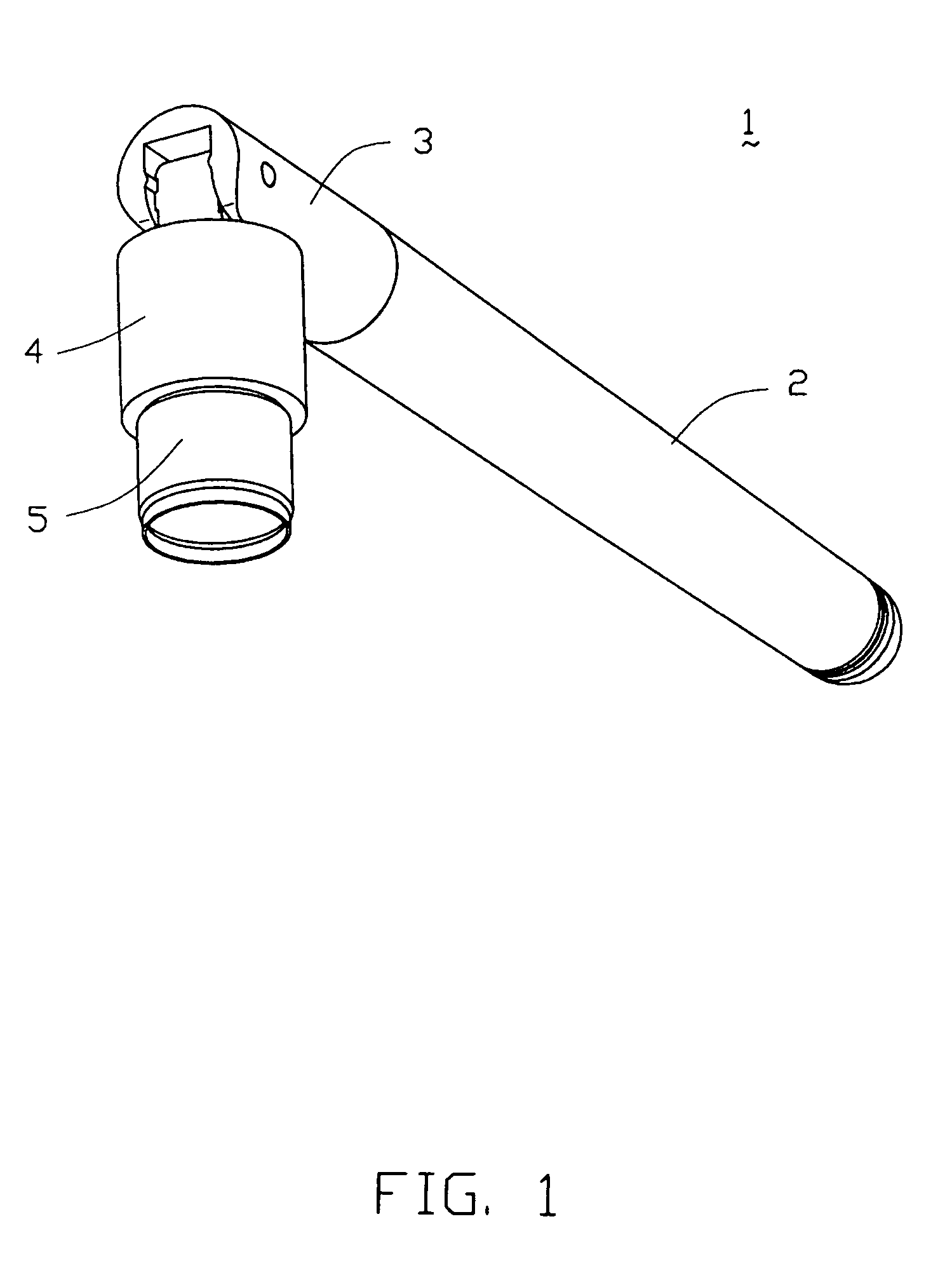
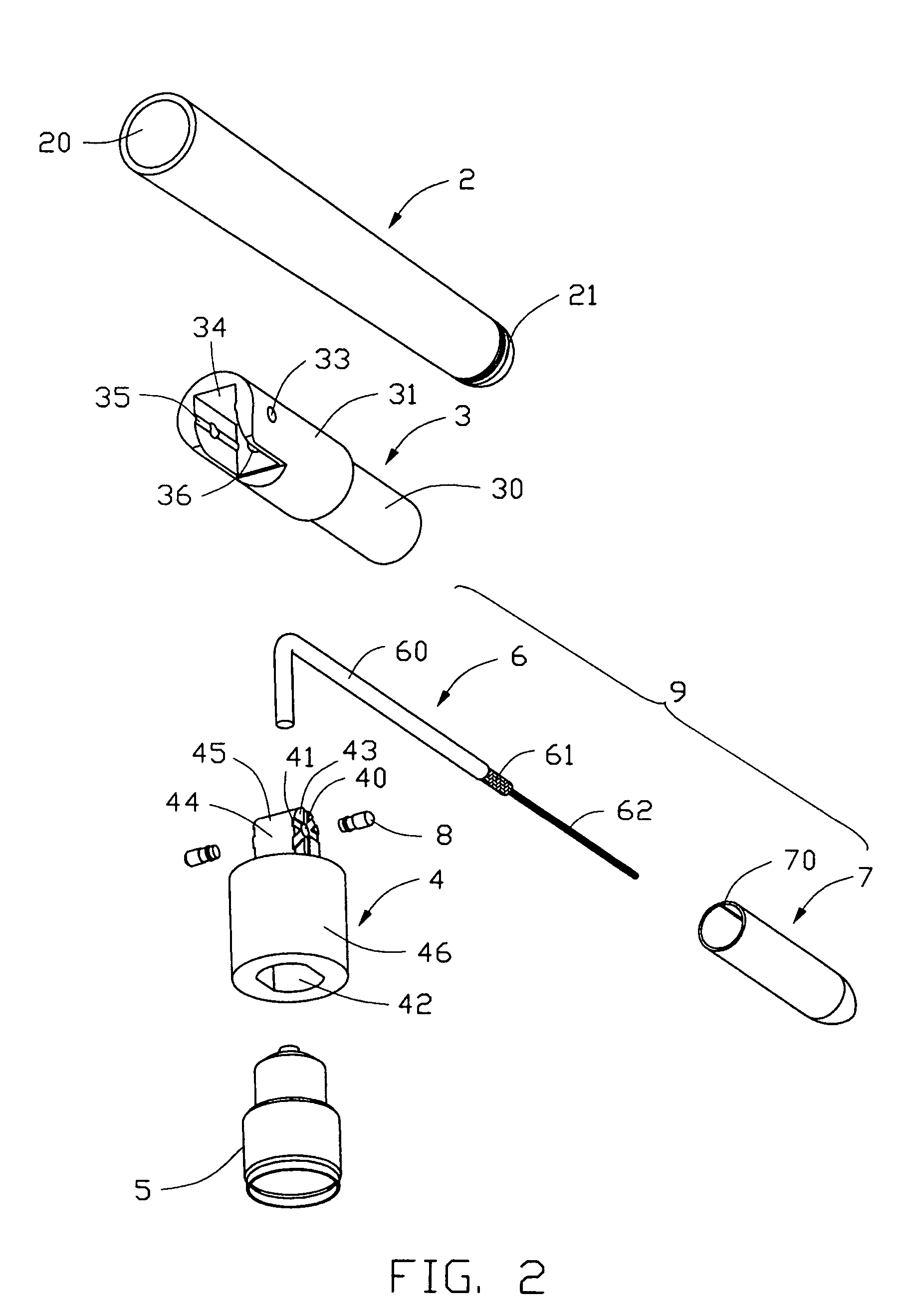
[0016]Referring to FIGS. 1–3, a cable antenna assembly 1 according to a first preferred embodiment of the present invention comprises an outer sleeve 2, a rotating portion 3, a connecting portion 4, two bolts 8, and a cable antenna element 9 comprising a coaxial cable 6 and a grounding portion 7. The cable antenna assembly 1 is connecting to a corresponding connector (not shown), thereby connecting with an electronic device (not shown) via a connector 5. The connector 5 is well known to the ordinary skills in the art, so a detail description of the connector 5 is omitted here.

[0017]The outer sleeve 2 is an elongate tubular sleeve and is made of insulative material. The outer sleeve 2 has an open end 20 and a closed end 21. The outer sleeve 2 is provided for surrounding and protecting the main antenna body 9.

[0018]The connecting portion 4 is made of insulative material and is connected to the...


PUM


Abstract

A cable antenna assembly (1) connecting with an electronic device via a connector (5) includes a connecting portion (4), a rotating portion (3) rotatably mounted on the connecting portion, and a cable antenna element (9) including a coaxial cable (6) including an inner conductor (62), an inner insulator, an outer conductor (61) and an outer insulator (60), and a grounding sleeve (7) surrounding the coaxial cable and inserted between an inner and an outer rings (30a) and (30b) of the rotating portion. The grounding sleeve defines a fixing hole (71) for connecting with the outer conductor of the coaxial cable and a slot (70) for making the fixing hole elastically expand when the coaxial cable is inserted and then elastically contract for securely fixing the coaxial cable.

Description

BACKGROUND OF THE INVENTION[0001]1. Field of the Invention[0002]The present invention concerns generally the practical field of an antenna assembly, and especially concerns a cable antenna assembly.[0003]2. Description of the Prior Art[0004]Wireless connection between information appliances, such as notebook computers and mobile phones, and network systems, is becoming a modern trend for information appliances. An antenna is required for facilitating wireless connection. Since the information appliances usually have a small size, a conventional antenna occupying a great amount of space is not suitable for such an application. Thus antennas made of coaxial cables that are widely used in information appliances are prevailing. A coaxial cable antenna may comprise at least one coaxial cable having a first end connected to a signal processing circuit of the information appliance and a second end exposed for receiving / transmitting electromagnetic signals.[0005]A cable antenna is disclosed...

Claims


Application Information

Patent Timeline
Patent Type & Authority Patents(United States)
IPC IPC(8): H01Q1/24H01Q1/38H01Q1/08H01Q1/22H01Q1/50H01Q9/04H01Q9/16H01Q9/30
CPCH01Q1/084H01Q1/2258H01Q9/16H01Q9/30H01Q1/242Y10S439/916
Inventor LIU, HUANG HSIN
Owner HON HAI PRECISION IND CO LTD
Learn More