
Stereomicroscopy method and stereomicroscopy system

a stereomicroscopy and microscopy technology, applied in the field of stereomicroscopy methods and stereomicroscopy systems, can solve the problems of limiting the effect of users' position and the direction of view of objects onto objects

Inactive Publication Date: 2007-03-20
CARL-ZEISS-STIFTUNG TRADING AS CARL ZEISS
View PDF32 Cites 17 Cited by
  • Summary
  • Abstract
  • Description
  • Claims
  • Application Information

AI Technical Summary

Benefits of technology

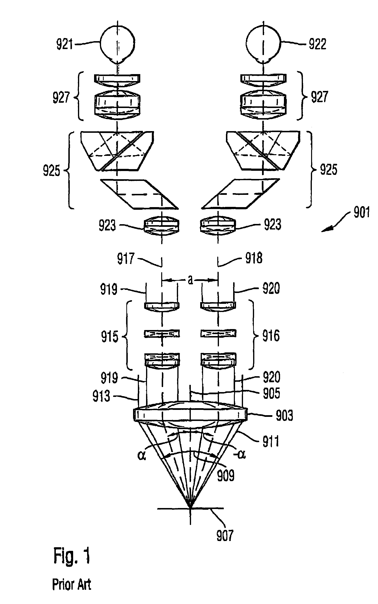
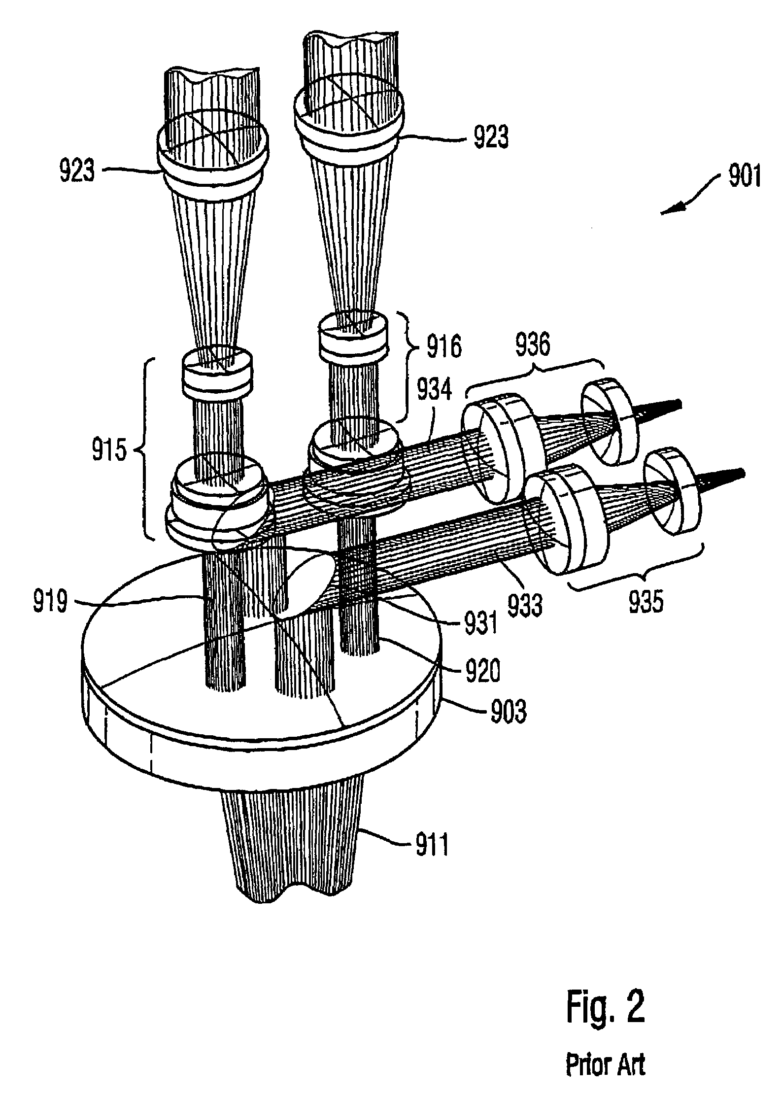
[0008]To this end, the invention proceeds from the finding that in the conventional microscopes shown in FIGS. 1 and 2 the radiation emanating from the object and processed by the objective, that is, the radiation emanating from the object towards the objective in the solid angle region and the parallel beam bundle passed on by the objective, respectively, comprise sufficient spatial information about the object to allow to produce therefrom stereoscopic representations of the object from a plurality of directions of view onto the object. Furthermore, it was found that merely the conventional way of using the information contained in the radiation emanating from the object, that is, the feeding of individual partial beam bundles out of the complete parallel beam bundle by the zoom systems and mirrors of the conventional microscopes shown in FIGS. 1 and 2 has a limiting effect on the position of the users and the directions of view thereof onto the object.
[0010]The image data are produced from the radiation data dependent upon the two determined locations, that is, a virtual direction of view of the user onto the object. In this respect, it is, in particular, also possible to already carry out the detection of the radiation emanating from the object dependent upon these two locations so that the conversion of radiation data into the image data can be performed with more ease, or the radiation data can be used directly as image data.
[0018]If the partial region of the object which is also observed by the second camera is positioned centrally in the region of the object observed by the first camera, the user will perceive a three-dimensional, stereoscopic representation of the object with increased resolution in the center of his field of view. At the edge of his field of view he will perceive merely a two-dimensional representation of reduced resolution. The lack of a stereoscopic representation at the edge of the field of view is not always felt as disadvantageous by the user, while the increased resolution in the center of the field of view is perceived as advantageous.

Problems solved by technology

Furthermore, it was found that merely the conventional way of using the information contained in the radiation emanating from the object, that is, the feeding of individual partial beam bundles out of the complete parallel beam bundle by the zoom systems and mirrors of the conventional microscopes shown in FIGS. 1 and 2 has a limiting effect on the position of the users and the directions of view thereof onto the object.

Method used


Image

  • Stereomicroscopy method and stereomicroscopy system
  • Stereomicroscopy method and stereomicroscopy system
  • Stereomicroscopy method and stereomicroscopy system

Examples


Embodiment Construction

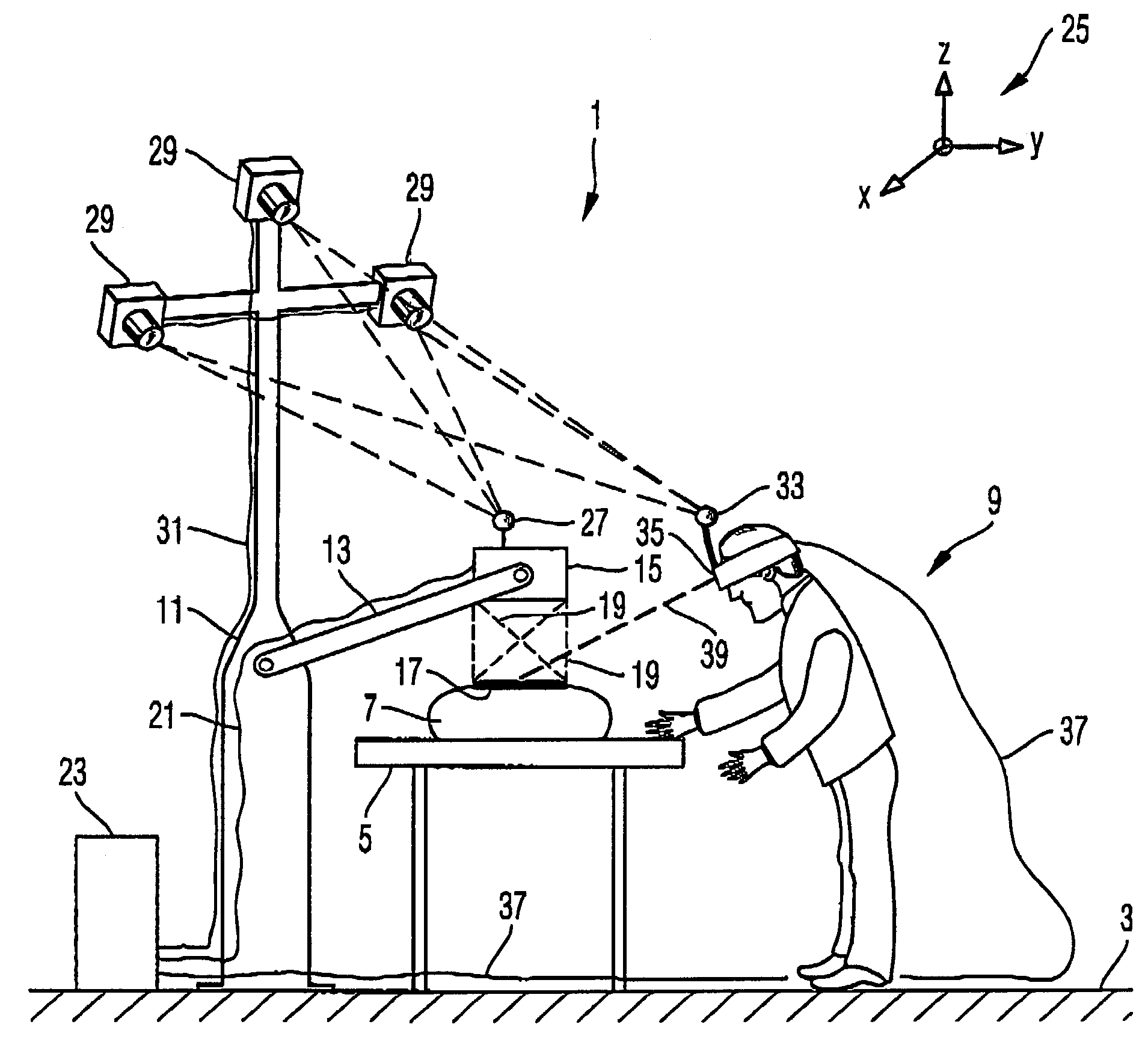
[0033]FIG. 3 shows an operating room in which a stereomicroscopy system 1 according to the invention is installed. An operating table 5, on which a patient 7 lies on whom a microsurgery is being performed by a surgeon 9, is fixedly mounted on a floor 3 of the operating room. A stand 11 is fixedly mounted on the floor 3 of the operating room, said stand 11 pivotally holding a topography detection apparatus 15 on a pivotal arm 13 which is positioned above the patient 7 such that the topography detection apparatus 15 can record a surface geometry or topography of a region 17 of the patient 7. The topography detection apparatus 15 operates optically. In FIG. 3 optical beams which emanate from the region 17 of the patient 7 and are recorded by the topography detection apparatus 15 are schematically shown as dotted lines 19.

[0034]The topography detection apparatus 15 obtains radiation data from this radiation 19 which are transmitted to a computer 23 via a data line 21. On the basis of th...


PUM


Abstract

A stereomicroscopy system and method for generating at least a pair of representations of an object 7 for observation a user 9 are provided, comprising a detection system 15 for providing radiation data corresponding to detected radiation emanating from a region 17 of the object, a position detection apparatus 29 for detecting a position of the user, a location determination device 23 for determining a first and a second location in an object coordinate system 25, an image data generation device 23 for generating image data from the radiation data for a first representation and a second representation representing the region of the object viewed from the first and second locations, respectively, and a display apparatus 75 for displaying the first representation for a left eye of the user and for displaying the second representation for a right eye of the user as a function of the image data.

Description

FIELD OF THE INVENTION [0001]The invention relates to a stereomicroscopy method and a stereomicroscopy system for producing at least a pair of representations of an object to be viewed by at least one user.BACKGROUND OF THE INVENTION[0002]The stereomicroscopy method according to the invention and the stereomicroscopy system according to the invention serve to produce stereoscopic representations of an object such that, when viewing the representations, the user obtains a three-dimensional impression of the representations. To this end, it is necessary for the left eye and the right eye of the user to perceive different representations of the object from different directions of view onto the object.[0003]An example of a conventional stereomicroscopy system is a stereomicroscope. A beam path of a conventional stereomicroscope is schematically shown in FIG. 1. The stereomicroscope 901 shown there comprises an objective 903 with an optical axis 905 and an object plane 907 in which an ob...

Claims


Application Information

Patent Timeline
IPC IPC(8): G02B21/22A61B5/05G02B21/00A61B19/00G02B21/36G02B27/22G06T19/00H04N7/18H04N13/00
CPCG02B21/22H04N13/021H04N13/0239H04N13/0253H04N13/0468H04N13/0285H04N13/044H04N13/211H04N13/344H04N13/254H04N13/366H04N13/286H04N13/239
Inventor HAISCH, MICHAELMONZ, LUDWIN
Owner CARL-ZEISS-STIFTUNG TRADING AS CARL ZEISS
Learn More