
Angled flat-type recording head designed for near-constant resolution at varying type velocities

a flat-type, near-constant resolution technology, applied in the field of flat-profile tape recording heads, can solve the problems of shortening the surface length of the tape bearing, increasing the fly height, and increasing the wear of the head, so as to achieve more effective straightening

Inactive Publication Date: 2007-03-20
IBM CORP
View PDF16 Cites 21 Cited by
  • Summary
  • Abstract
  • Description
  • Claims
  • Application Information

AI Technical Summary

Benefits of technology

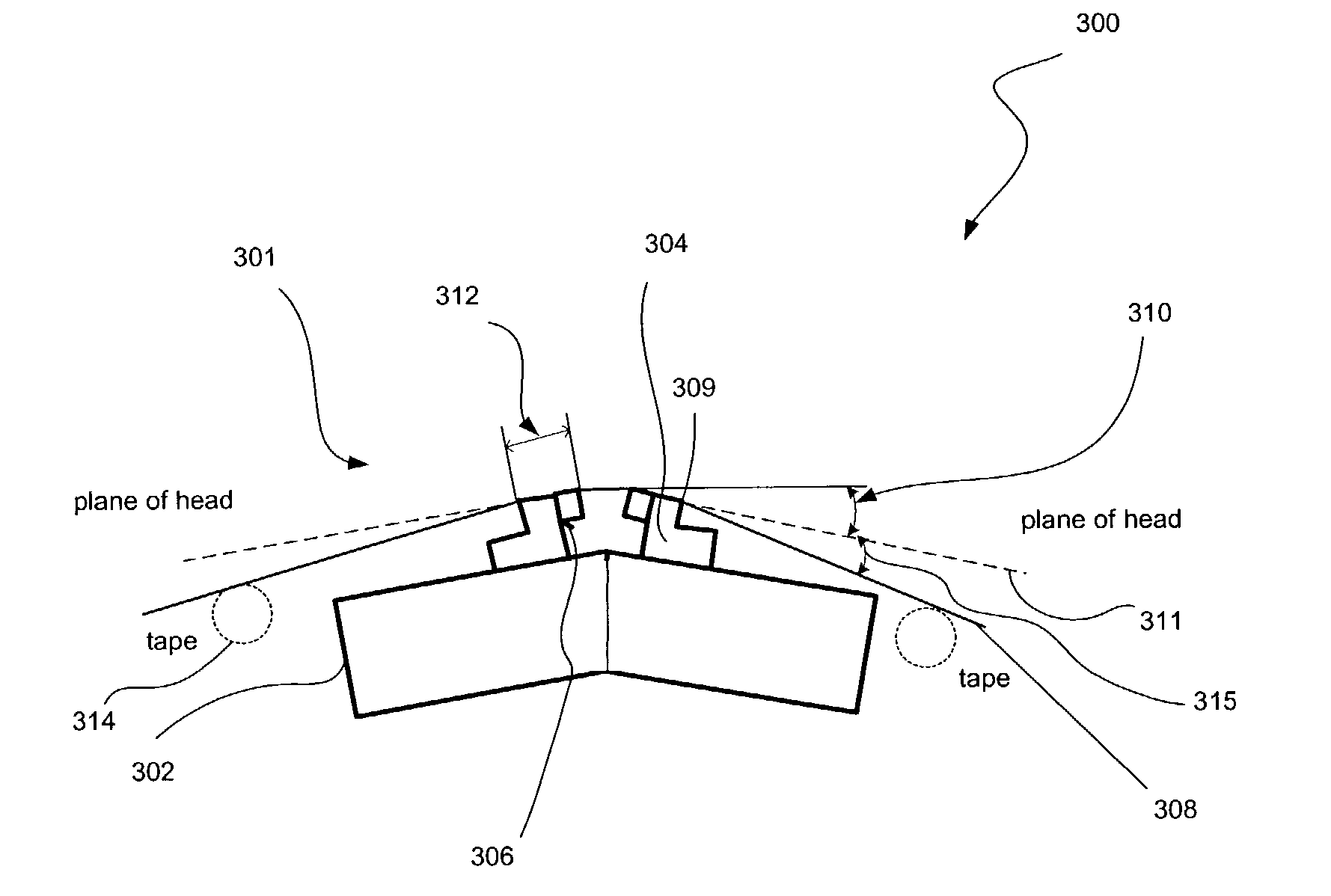
[0018]The present embodiment solves the problems of the prior art by shortening the tape bearing length in the direction of tape travel. A shorter length makes a given wrap angle more effective at straightening with respect to the curl, as the head tends to behave more like a smaller radius cylinder.

Problems solved by technology

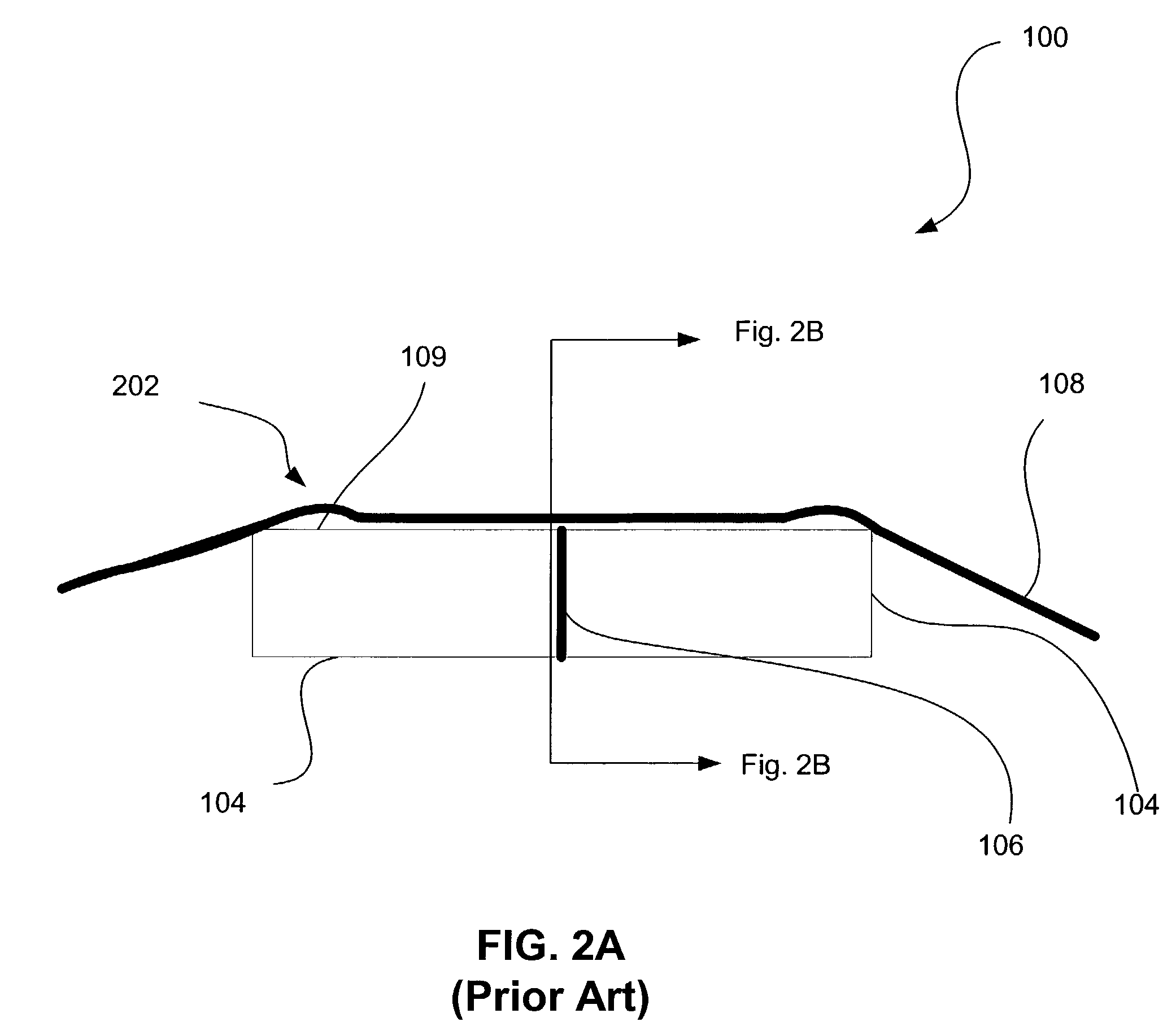
Still yet, the tape lifting 204 results in additional stress at points 206 which, in turn, causes additional wear.
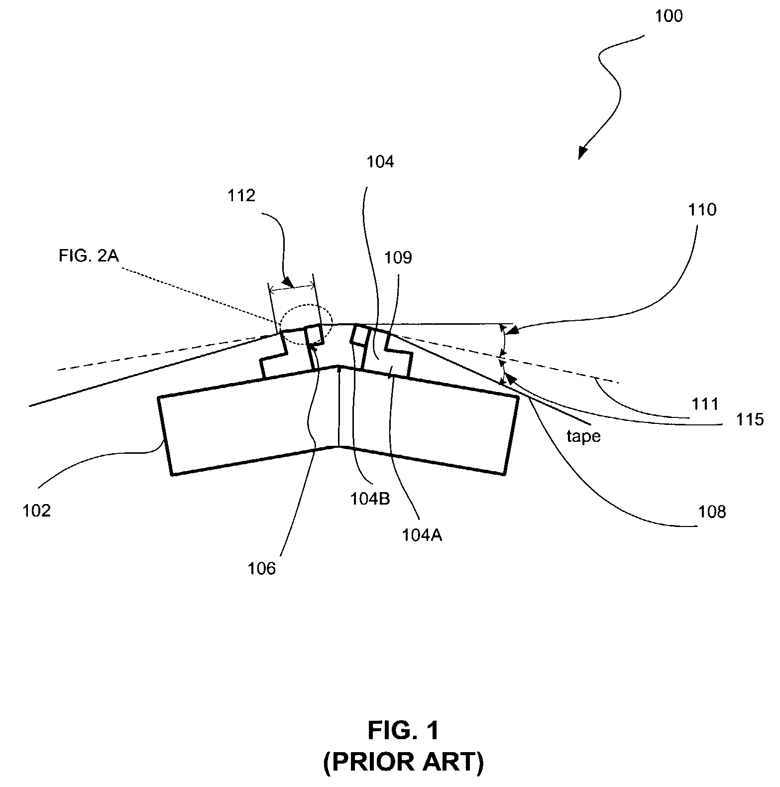
Moreover, wear of the edges of the tape bearing surface 109 may result in shortening of the tape bearing surface length 112 over time.
In particular, increasing tape speed of those tapes causes an increase in fly height, and thus a decrease in high frequency output.
This means that in applications requiring “speed matching” in which drive speed varies in response to user-attached system speed, error rates may change with tape speed.
Modeling and experiments have shown that at any tape speed larger tents tend to suck more air into the head-tape interface and thus results in an increase in head-tape separation in the region of the recording head.
If the tape appears dynamically stiffer as speed increases due to viscoelasticity, larger tents and a greater fly height may result.
Increasing the tape wrap angle tends to “straighten” the wrapping and generally reduce edge lifting, but this has the negative effect already described hereinabove.

Method used


Image

  • Angled flat-type recording head designed for near-constant resolution at varying type velocities
  • Angled flat-type recording head designed for near-constant resolution at varying type velocities
  • Angled flat-type recording head designed for near-constant resolution at varying type velocities

Examples


Embodiment Construction

[0028]The following description is the best embodiment presently contemplated for carrying out the present invention. This description is made for the purpose of illustrating the general principles of the present invention and is not meant to limit the inventive concepts claimed herein.

[0029]FIG. 3 illustrates a flat-lapped magnetic tape head system 300, in accordance with one embodiment. As shown, a pair of head assemblies 301 is provided each with a base 302 that is equipped with a row bar 304 each including a substrate and a closure with a reader / writer head 306 situated therebetween. The row bar 304 and the base 302 may be integrally coupled as a unitary unit or include two separate components coupled together. In the context of the present description, the row bar 304 may include any portion of the head assemblies 301 to which the head 306 is attached.

[0030]A tape 308 is moved along a tape bearing surface 309 in the manner shown for reading and writing data on the tape 308 usin...


PUM

PropertyMeasurementUnit
Lengthaaaaaaaaaa
Lengthaaaaaaaaaa
Lengthaaaaaaaaaa

Abstract

A magnetic tape head system and associated method are disclosed. Included is one or more head assemblies each including a base with a row bar coupled thereto with a head situated therein for defining a tape bearing surface defining a tape wrap angle with respect to a horizontal plane. A length of the tape bearing surface is between approximately 0.57 millimeters and 0.7 millimeters and the tape wrap angle is between approximately 0.5 degrees and 1.3 degrees such that a resolution of the magnetic tape head system is substantially independent of a velocity of the tape.

Description

FIELD OF THE INVENTION[0001]The present invention relates to magnetic recording heads, and more particularly, this invention relates to flat profile tape recording heads.BACKGROUND OF THE INVENTION[0002]Prior Art FIG. 1 illustrates a traditional flat-lapped bi-directional, two-module magnetic tape head 100, in accordance with the prior art. As shown, a pair of bases 102 is equipped with row bars 104 each including a substrate 104A and a closure 104B with readers and writers 106 situated therebetween. In use, a tape 108 is moved over the row bars 104 along a tape bearing surface 109 in the manner shown for reading and writing data on the tape 108 using the readers and writers 106. Conventionally, a partial vacuum is formed between the tape 108 and the tape bearing surface 109 for maintaining the tape 108 in communication with the readers and writers 106. More information regarding such flat-lapped magnetic tape head may be found with reference to U.S. Pat. No. 5,905,613, which is inc...

Claims


Application Information

Patent Timeline
IPC IPC(8): G11B5/187G11B5/265G11B5/53
CPCG11B5/532Y10T29/49021Y10T29/49032Y10T29/49028
Inventor BISKEBORN, ROBERT GLENN
Owner IBM CORP
Learn More