Integrated heat removal and vibration damping for avionic equipment

a technology of avionic equipment and thermal management, applied in the direction of slidable card holders, insulated conductors, cables, etc., can solve the problems of minimal thermal transfer, undesirable weight increase, and significant increase in manufacturing costs and weight of each pwb, and achieves the effect of increasing thermal management and structural support, and being inexpensive and lightweigh

Inactive Publication Date: 2007-03-20
HAMILTON SUNDSTRAND CORP
View PDF12 Cites 48 Cited by
  • Summary
  • Abstract
  • Description
  • Claims
  • Application Information

AI Technical Summary

Benefits of technology

[0008]The present invention therefore provides an electronics equipment rack system which increases the thermal management and structural support of a printed wiring board in an inexpensive and lightweight package.

Problems solved by technology

Although providing effective thermal management, incorporating additional cooling conductors within the PWBs may significantly increase the manufacturing expense and weight of each PWB.
However, the thinness of the PWBs results in a relatively flexible structure which may deflect in response to the vibratory inputs of typical aircraft operating environments.
This thinness results in minimal thermal transfer.
However, increasing the size of the structural stiffener to provide thermal transfer through conduction would result in an undesirable weight increase.

Method used


Image

  • Integrated heat removal and vibration damping for avionic equipment
  • Integrated heat removal and vibration damping for avionic equipment
  • Integrated heat removal and vibration damping for avionic equipment

Examples


Embodiment Construction

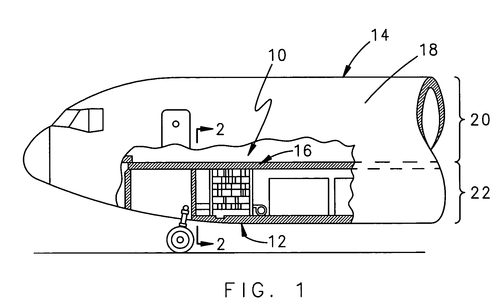
[0017]FIG. 1 illustrates a general schematic view of an avionics system 10 mounted with an avionics bay 12 of an aircraft 14. It should be understood that various locations for the avionics bay will benefit from the present invention and that the present invention is not limited to just aircraft environments as various vehicles and stationary emplacements which utilize electronic mountings will benefit from the present invention.

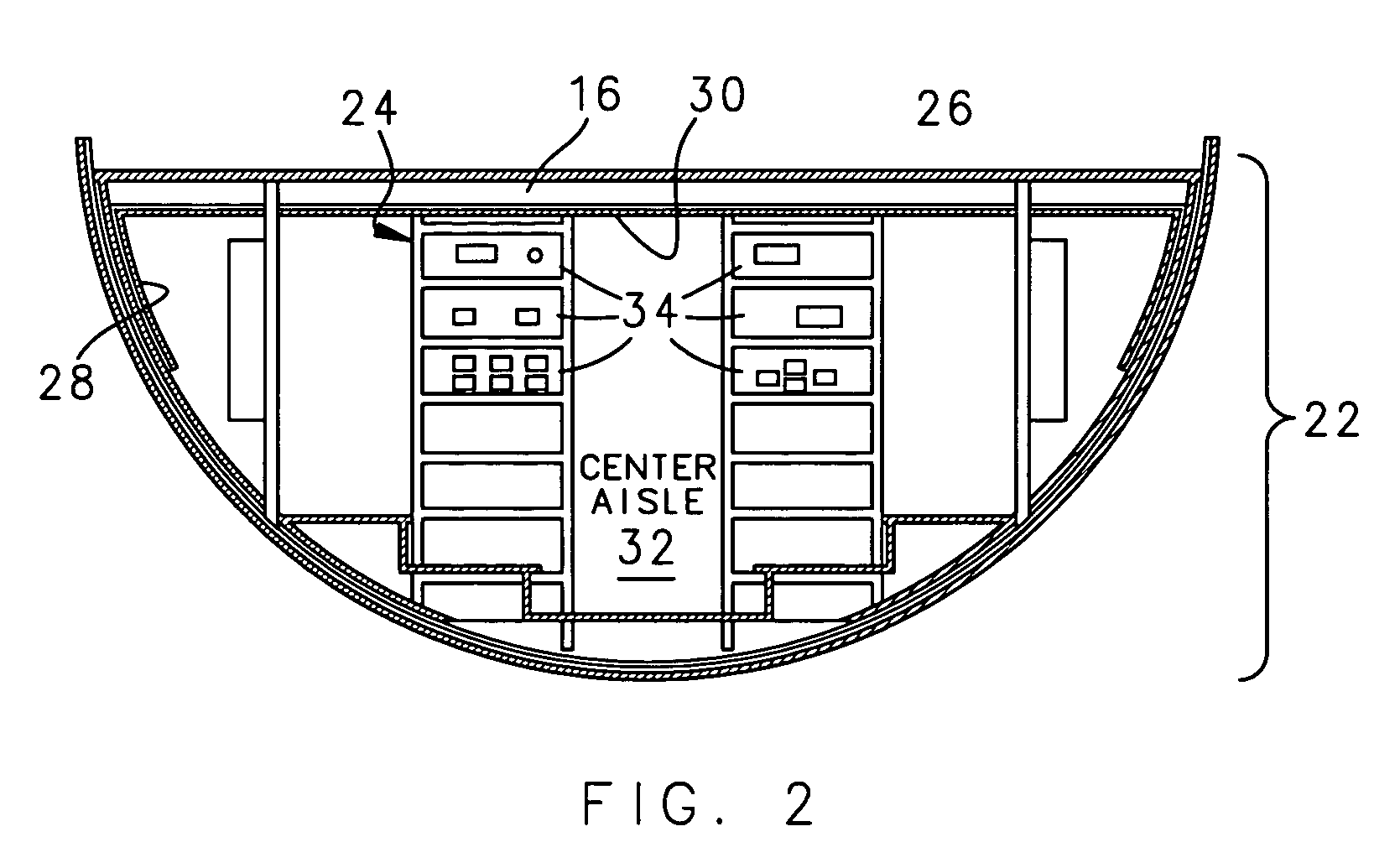
[0018]Typically, the aircraft includes a horizontal deck 16 that extends substantially along the length of an aircraft fuselage 18 to divide the fuselage into an upper, passenger carrying lobe 20 and a lower equipment and cargo lobe 22. The avionics bay 12 is typically positioned within the lower lobe 22. It should be understood that although a particular component arrangement for mounting in a rack is disclosed in the illustrated embodiment, other arrangements will benefit from the instant invention.

[0019]Referring to FIG. 2, the bay 12 includes two electro...


PUM


Abstract

An electronic equipment rack system supports a printed wire board (PWB) assembly having a structural stiffener with a heat pipe mounted therein. The heat pipe is mounted within the structural stiffener directly adjacent the printed wire board to conduct thermal energy away from the electronic components on the printed wire board.

Description

BACKGROUND OF THE INVENTION[0001]The present invention relates to the mounting of electrical and electronic equipment, and more particularly to mounting and thermal management of avionic systems.[0002]Avionic systems are mounted within an aircraft electronics bay to provide reliability and serviceability. Significant considerations of avionic system mounting are the thermal management and structural support thereof.[0003]Avionic systems commonly include a multitude of printed wiring board assemblies (PWBs) mounted within electronic equipment racks. The construction of the racks typically includes integrated thermal management schemes such as edge cooling. Edge-cooling allows the heat produced in an electronic circuit to be rejected by conduction through the PWB surface and communicated to the PWB edges. The PWB edges are mounted in the rack and are cooled by flowing liquid or air adjacent thereto. Depending on the required heat dissipation level of the electronic circuit, additional...

Claims


Application Information

Patent Timeline
Patent Type & Authority Patents(United States)
IPC IPC(8): H05K7/20
CPCH05K7/20672H05K7/1461
Inventor PAL, DEBABRATA
Owner HAMILTON SUNDSTRAND CORP
Why Eureka
Try Eureka