Holding mechanism of an optical disk clamper and an optical disk drive using the same

a technology holding mechanism, which is applied in the field of optical disk clamper, can solve the problems of restricted range of clearance in which the optical disk clamper can move in the holding mechanism of the optical disk clamper

Inactive Publication Date: 2007-03-20
MITSUMI ELECTRIC CO LTD
View PDF11 Cites 5 Cited by
  • Summary
  • Abstract
  • Description
  • Claims
  • Application Information

AI Technical Summary

Benefits of technology

[0018]Accordingly, it is an object of the present invention to provide a novel and useful optical disk clamper holding unit and an optical disk drive by which the problem described above is eliminated.

Problems solved by technology

Compared to the conventional optical disk clamper holding unit, the range of clearance in which the optical disk clamper can move in the optical disk clamper holding mechanism is restricted.

Method used


Image

  • Holding mechanism of an optical disk clamper and an optical disk drive using the same
  • Holding mechanism of an optical disk clamper and an optical disk drive using the same
  • Holding mechanism of an optical disk clamper and an optical disk drive using the same

Examples


Embodiment Construction

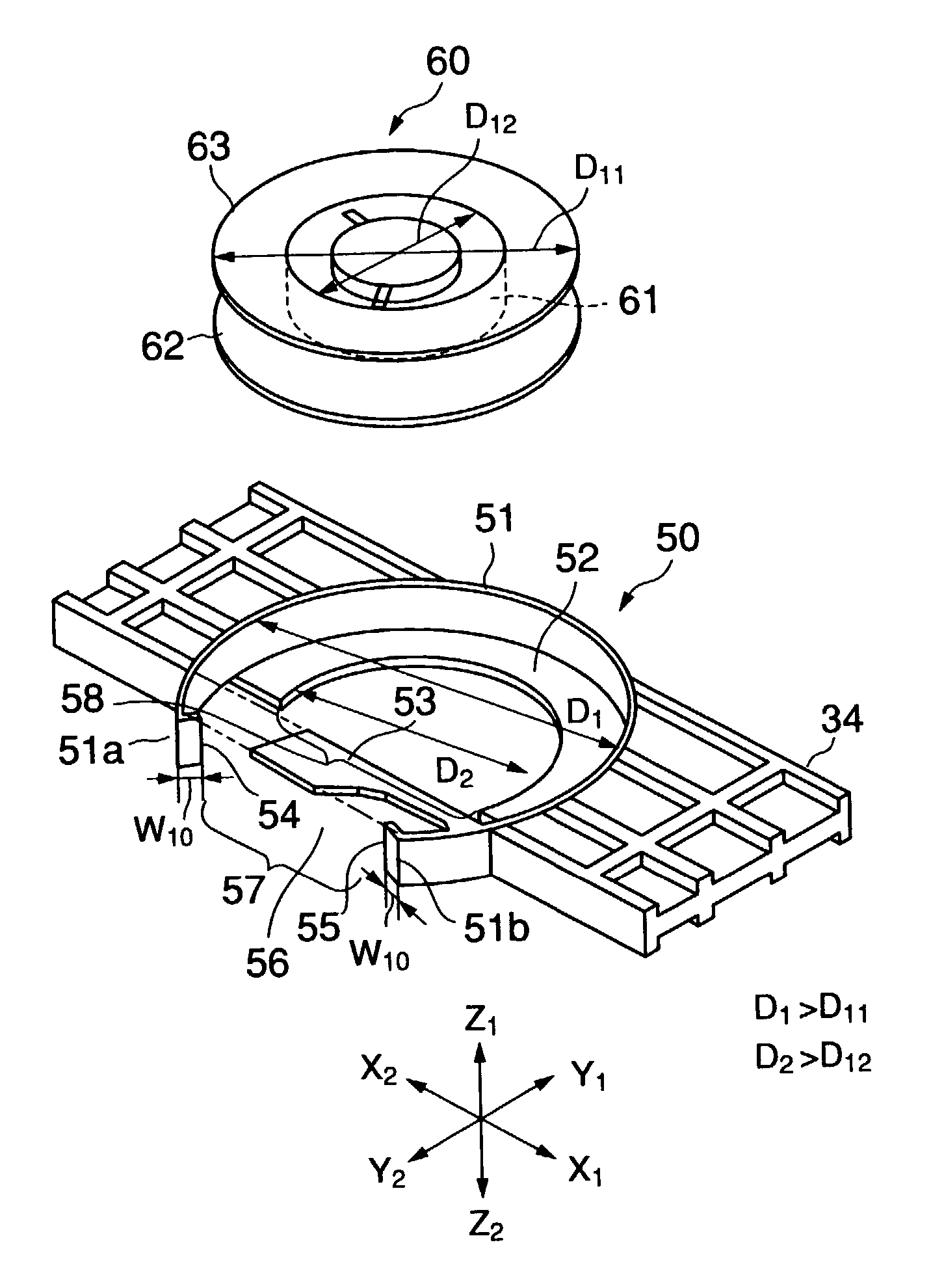
[0042]A description of the preferred embodiments of the present invention will be given after a brief description of an optical disk drive. FIG. 4 is a top view showing an optical disk drive 30. A disk tray and an optical base unit assembly are not shown in FIG. 4. FIGS. 5A and 5B are side views showing the optical disk drive 30. The disk tray is not shown. The arrow X1-X2 indicates the width direction of the optical disk drive 30; the arrow Y1-Y2 indicates the depth direction of the optical disk drive 30; and the arrow Z1-Z2 indicates the height direction of the optical disk drive 30.

[0043]The optical disk drive 30 includes a housing 31 that is a box made of synthetic resin, a disk tray (not showed), and an optical base unit assembly 40. The optical disk drive 30 is horizontally built into the system unit of a computer and so forth.

[0044]The optical base unit assembly 40 is provided with a square supporting base 41, a turn table 42, a motor 43 that rotates the turn table 42, an opt...


PUM

PropertyMeasurementUnit
widthaaaaaaaaaa
distanceaaaaaaaaaa
heataaaaaaaaaa

Abstract

An optical disk clamper holding mechanism that holds an optical disk clamper includes a surrounding unit, a flange unit, a rib that touches, when the optical disk clamper moves in the direction of the flange opening, a rim portion of an upper flange unit of the optical disk clamper, the rib protruding inwardly at a position opposite to the flange opening. Since the range of clearance in which the optical disk clamper can move in the optical disk clamper holding mechanism is restricted, the optical disk clamper always fits in the turntable normally and consequently, always clamps the optical disk normally.

Description

BACKGROUND OF THE INVENTION[0001]1. Field of the Invention[0002]The present invention generally relates to an optical disk clamper, and more particularly, to the retracting mechanism of an optical disk clamper and an optical disk drive using the same.[0003]2. Description of the Related Art[0004]A type of optical disk drive has an optical disk clamper held in a holding unit. When an optical disk is set in such type of optical disk drive, a turntable moves upward and the optical disk clamper fits in and is magnetically attracted by the turntable so that the optical disk is clamped on the turntable. The optical disk clamper holding unit has an opening portion through which the optical disk clamper is built in, but supports the optical disk clamper so that the optical disk clamper does not come out once built in.[0005]FIGS. 1A–1C are schematic diagrams showing a conventional optical disk clamper holding unit 10. This optical disk clamper holding unit 10 has a surrounding unit 11, a flan...

Claims


Application Information

Patent Timeline
Patent Type & Authority Patents(United States)
IPC IPC(8): G11B17/022G11B17/028G11B33/14
CPCG11B17/0285G11B33/14
Inventor OGASAWARA, MANABU
Owner MITSUMI ELECTRIC CO LTD
Why Eureka
Try Eureka