Clothes drier

a drying machine and cloth technology, applied in drying machines, lighting and heating equipment, drying machines, etc., can solve the problems of slow temperature rise by the compressor, difficult to return to the original temperature of warm air, compressor starting failure, etc., to reduce the effect of compressor suspension and load reduction

Inactive Publication Date: 2007-03-27
PANASONIC CORP
View PDF8 Cites 28 Cited by
  • Summary
  • Abstract
  • Description
  • Claims
  • Application Information

AI Technical Summary

Benefits of technology

[0005]It is, therefore, an object of the present invention to provide a clothes drying apparatus capable of reducing a load on a compressor by avoiding a frequently repeated stop and restart of the compressor during a short time period even in case a heat pump mechanism including the compressor is employed as a heat source, and allowing the temperature of warm air to rapidly return by using the heat pump mechanism, wherein the clothes drying apparatus can handle a suspension of the drying operation during a drying process, an opening / closing of a door and a loading / unloading of clothes, all of which are unique characteristics of using a drying apparatus in order to, e.g., check a dried state of clothes during the drying process, take out dried clothes or easily wrinkled clothes and add clothes to be dried during the drying process.
[0007]Due to such delay time period of suspension, it is possible to avoid the frequently repeated stop and start of the compressor during a short time period and reduce a load on the compressor, thereby reducing the effect of a suspension of a drying operation during a drying process.
[0008]A clothes drying apparatus of the present invention reduces a load on a compressor even in case a heat pump mechanism having the compressor serving as a heat source is employed, thereby reducing the effect of a suspension of a drying operation.
[0010]Since the compressor has a certain delay time period, time can be made available until a pressure difference of the coolant decreases after compressor has stopped. Accordingly, a load on compressor is reduced, and a frequently repeated stop and restart of compressor during a short time period can be avoided, thereby reducing the effect of the suspension of the drying operation.

Problems solved by technology

However, in case a heat pump mechanism including a compressor is employed as a heat source, raising temperature by the compressor is slow in comparison with a case of the electric heater and, further, it is difficult to return to an original temperature of warm air.
Furthermore, a pressure difference of a coolant in a refrigerating cycle of the heat pump mechanism becomes large shortly after the compressor stops, and a repeated stop and start during a short time period may lead to a starting failure of the compressor.

Method used


Image

  • Clothes drier
  • Clothes drier
  • Clothes drier

Examples


twelfth preferred embodiment

[0089](Twelfth Preferred Embodiment)

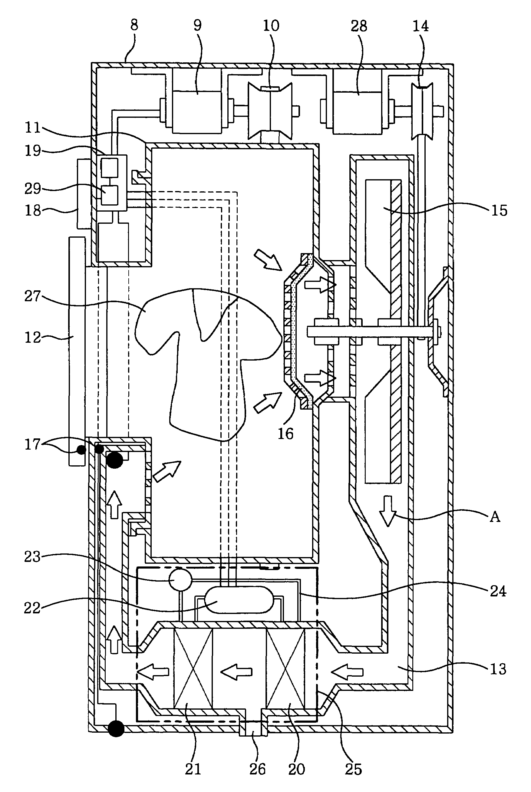
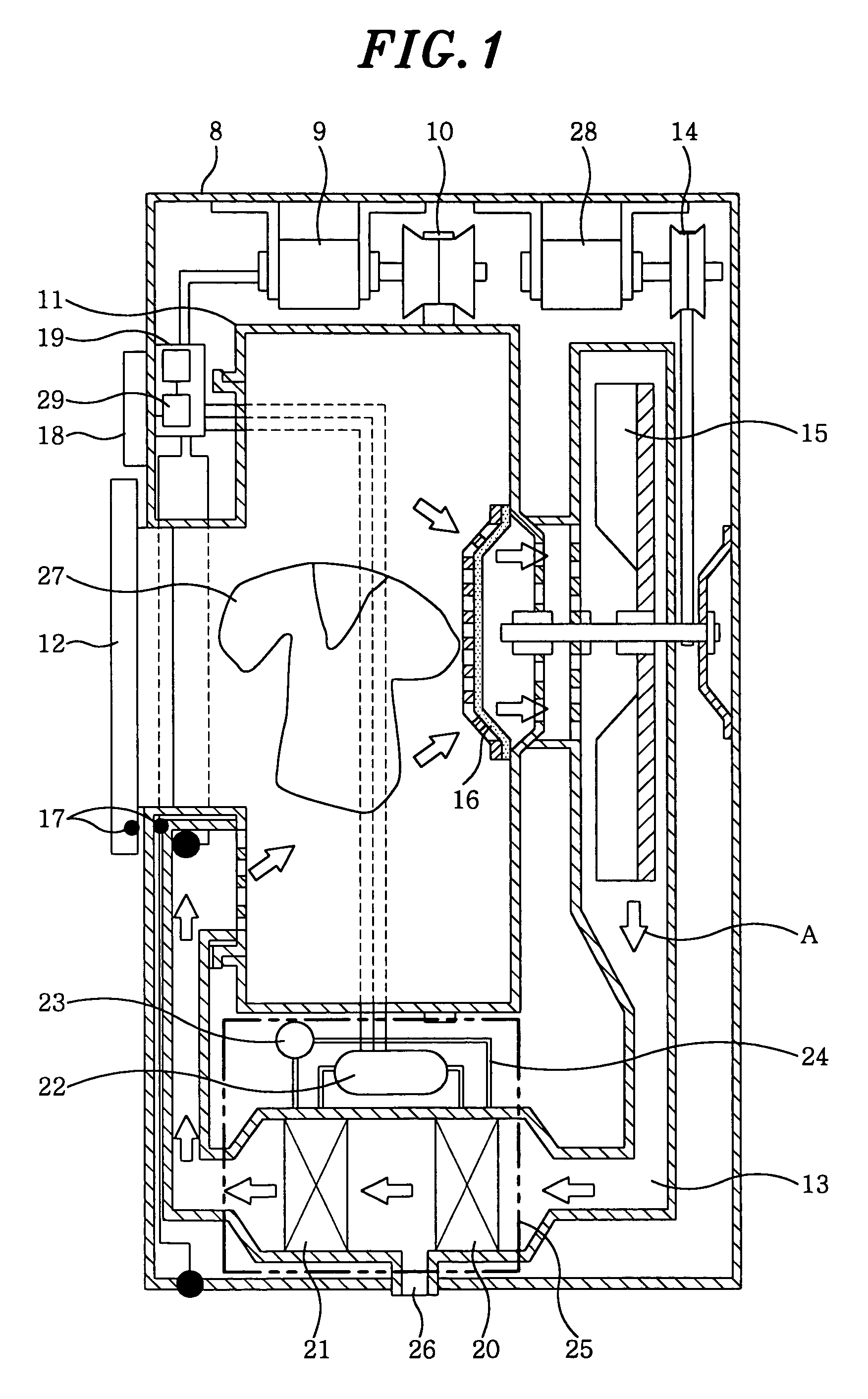
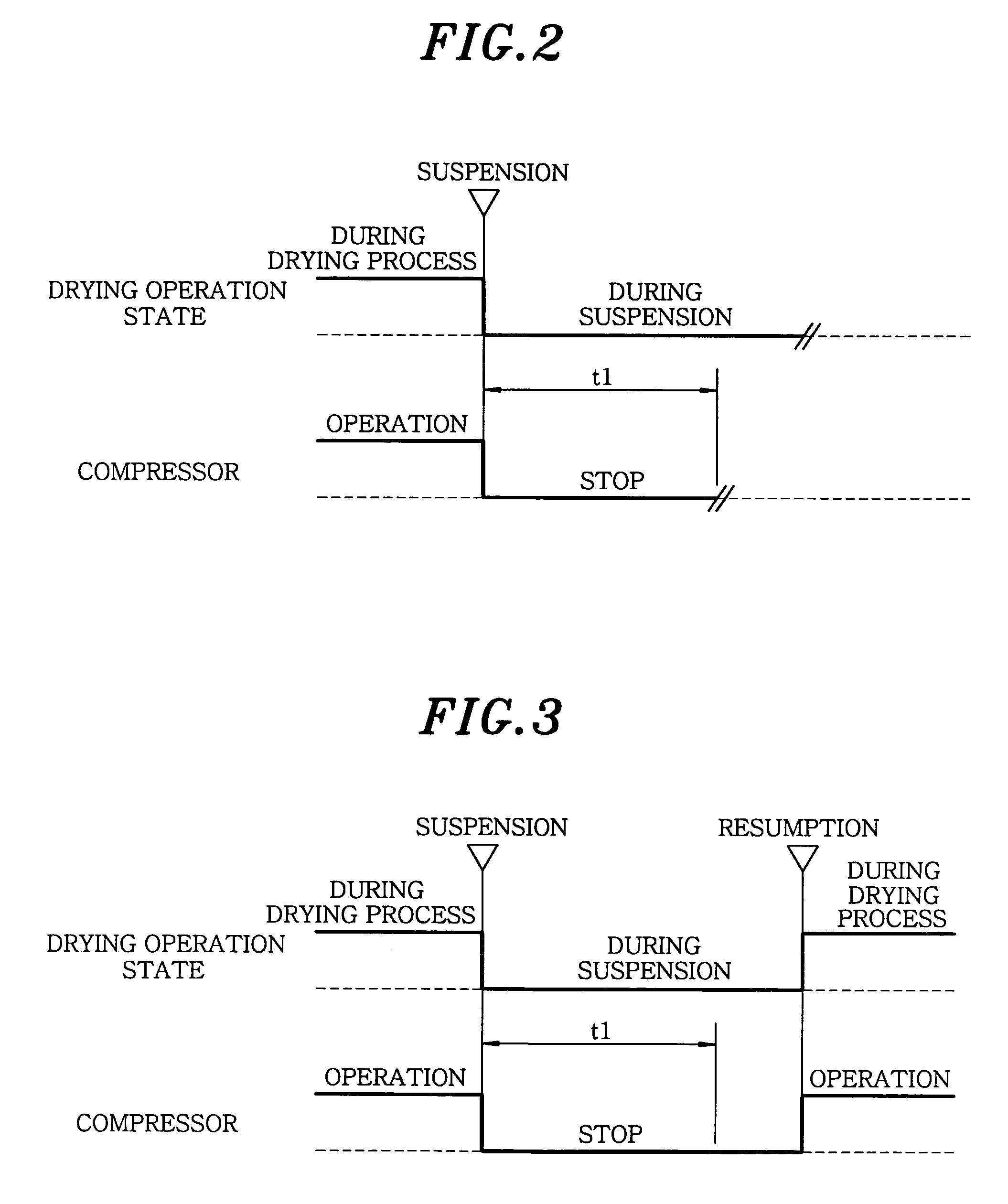
[0090]FIG. 13 illustrates a time chart depicting an operation performed when a drying operation of a clothes drier including a clothes drying apparatus in accordance with a twelfth preferred embodiment of the present invention is suspended. Since a basic operation and configuration of the clothes drier are the same as those of the first preferred embodiment, a detailed description thereof will be omitted.

[0091]Referring to FIG. 13, the first certain delay time period t1 is set to be longer than a time period to balance a high pressure side and a low pressure side of the coolant of compressor 22, which is specifically about three minutes. However, such pressure balancing time changes depending on a configuration and / or a capability of the heat pump mechanism and generally ranges from 30 seconds to five minutes. Since a certain delay time period of the compressor is provided in restarting the compressor in case the drying operation is resumed, the p...

thirteenth preferred embodiment

[0092](Thirteenth Preferred Embodiment)

[0093]In a thirteenth preferred embodiment, compressor 22 shown in FIG. 1 compresses a coolant in a cylinder in a reciprocating or a rotary type by rotating a DC motor. A compression capability is controlled in a manner that a rotation number of the DC motor is varied by inverter circuit 29 provided in controller 19.

[0094]By gradually increasing or reducing the compression capability of the compressor, it is easy to reduce the load on the compressor when it starts or stops.

[0095](Fourteenth Preferred Embodiment)

[0096]FIG. 14 shows a time chart illustrating an operation in which a drying operation of a clothes drier including a clothes drying apparatus in accordance with a fourteenth preferred embodiment of the present invention is resumed. Since a basic operation and configuration of the clothes drier are the same as those of the first preferred embodiment, a detailed description thereof will be omitted.

[0097]Referring to FIG. 14, controller 19...


PUM


Abstract

A clothes drying apparatus includes a heat pump mechanism, an air path for guiding drying air into a drying drum accommodating therein clothes, a blower for supplying drying air to the air path, and a controller for controlling a driving of a compressor, wherein the controller operates the blower and the compressor during a drying operation; stops the compressor in case the drying operation is suspended; and operates, in case the drying operation is resumed, the compressor after a certain time period has elapsed since the compressor had stopped. In case employing the heat pump mechanism having the compressor as a heat source, it is possible to reduce a load on the compressor and allow temperature of warm air to rapidly return by using the heat pump mechanism.

Description

FIELD OF THE INVENTION[0001]The present invention relates to a clothes drying apparatus included in a clothes drier for drying clothes or the like, or a washing and drying machine for washing and drying clothes in a same tub.BACKGROUND OF THE INVENTION[0002]In a conventional clothes drier, in case clothes are put into or taken out during a drying process or the like, a drying operation is suspended by opening / closing a door and the drying process is temporarily stopped, wherein all of a heating device, a blowing device and agitation blades are stopped (see, e.g., Japanese Patent Laid-open Publication No. H8-182897). FIG. 18 shows the conventional clothes drier disclosed therein. As illustrated in FIG. 18, the conventional clothes drier includes rotary drum 1 serving as a drying drum for accommodating and drying clothes and agitation blades; heat transfer fan having wings on both sides 2 for circulating warm air in rotary drum 1; self temperature control type PTC heater 3 serving as ...

Claims


Application Information

Patent Timeline
Patent Type & Authority Patents(United States)
IPC IPC(8): F26B21/00F26B21/06D06F58/20D06F58/24D06F58/28
CPCD06F58/206D06F2058/2874D06F2103/50D06F2105/26D06F2103/68D06F2105/62D06F2105/50D06F58/50D06F2103/40D06F2105/30D06F58/38
Inventor NAKAMOTO, SHIGEHARUYABUUCHI, HIDETAKANOJIMA, HAJIMETANAKA, MASAYUKI
Owner PANASONIC CORP
Why Eureka
Try Eureka