Jet weaving machine

a technology of weaving machine and loom, which is applied in the field of jet weaving machine, can solve the problems of space and weight saving, and achieve the effects of enhancing the cleaning effect, enhancing the cleaning action of thread or thread remnant on the optical sensor, and reducing the size of the loom

Inactive Publication Date: 2007-03-27
SULTEX AG
View PDF7 Cites 6 Cited by
  • Summary
  • Abstract
  • Description
  • Claims
  • Application Information

AI Technical Summary

Benefits of technology

[0017]It has also proved advantageous to provide a flexible connection line which is connected on the one hand to the capture tube and on the other hand to an inlet which opens into the suction device, preferably into the suction tube.
[0018]In particular in regard to the manipulation of weft thread insertion faults and the removal of incorrectly inserted weft threads it is a preferred measure for the suction device to comprise a disposal nozzle which can be charged with the fluid and which is arranged directly ahead of the tube monitor when viewed in the insertion direction. This disposal nozzle, which is preferably designed as a pressure nozzle or blowing nozzle, has the advantage that a greater drawing force can be exerted on faulty weft threads which must be removed from the shed.
[0019]In particular when using an electrostatic tube monitor it is particularly advantageous to arrange the disposal nozzle at or in the suction tube in such a manner that the fluid jet which is emitted by the disposal nozzle extends obliquely to the axis of the suction tube. Through this measure the thread to be disposed of is deflected in such a manner that it gives off its charge better to the tube monitor. The measure is furthermore advantageous if the tube monitor includes an optical sensor because the cleaning action of the thread or thread remnant on the optical sensor is enhanced.
[0020]In accordance with a particularly advantageous variant, the disposal nozzle and / or the inlet is arranged asymmetrically with respect to the longitudinal axis of the suction tube. Through the asymmetrical alignment of the disposal nozzle and / or of the inlet the thread or thread remnant receives a twist and moves rotatingly along the inner wall of the suction tube. In this way the cleaning effect can be enhanced and, in the case of an electronic tube monitor, the charge transfer to the tube monitor can be improved further.

Problems solved by technology

This means a considerable saving in space and weight.

Method used


Image

  • Jet weaving machine
  • Jet weaving machine
  • Jet weaving machine

Examples


Embodiment Construction

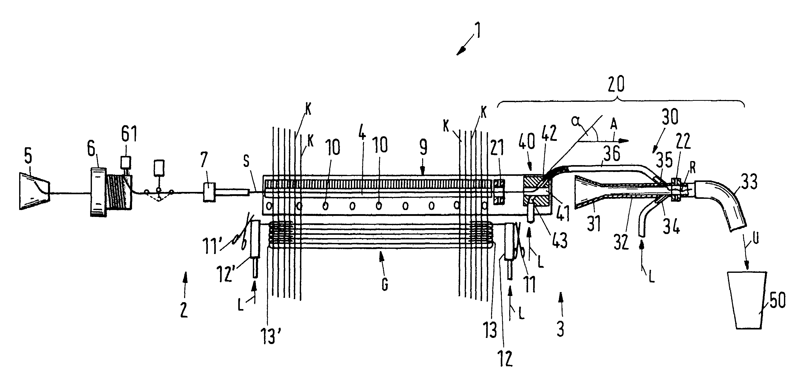
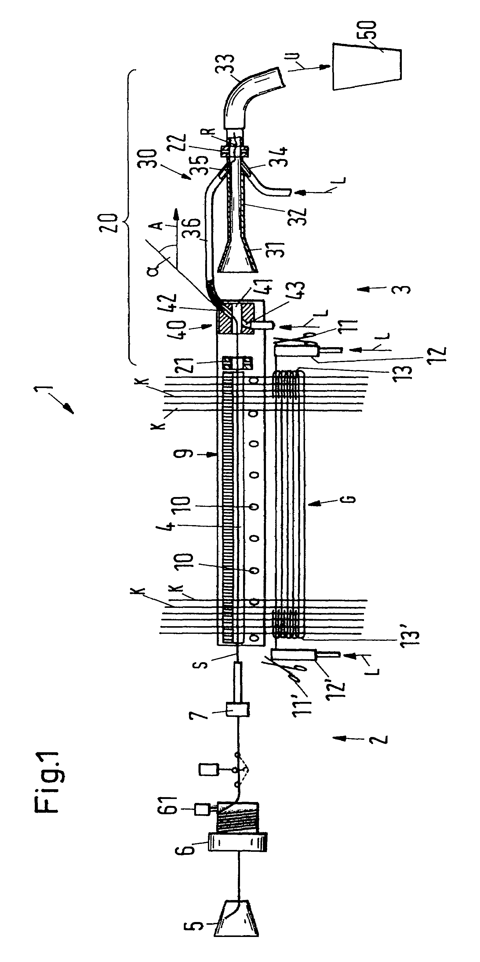
[0031]FIG. 1 shows in a schematic illustration essential parts of an exemplary embodiment of a jet weaving machine in accordance with the invention, especially an air jet weaving machine, which is designated in its entirety by the reference numeral 1. Components of the air jet weaving machine which are sufficiently known per se, such as the drive, warp beam, cloth draw off, electronic control and guidance devices etc., are not illustrated for the sake of better comprehensibility.

[0032]In the jet weaving machine 1 a weft thread S is inserted by means of a fluid, here air, from a weft insertion side 2 to a receiving side 3 along a weft insertion path 4. The weft insertion path 4 determines the weft insertion direction, which is indicated in FIG. 1 by the arrow A.

[0033]The jet weaving machine 1 comprises a thread bobbin 5, from which the weft thread S is drawn off by means of a non-illustrated winding apparatus and is deposited in the form of a plurality of windings onto a winding drum...


PUM


Abstract

A jet weaving machine is proposed in which a weft thread (S) can be inserted by means of a fluid from a weft insertion side (2) to a receiving side (3), including a weaving sley (9), along which a weft insertion path (4) extends, which determines a weft insertion direction (A), and including a monitoring apparatus (20) which is arranged at the receiving side (3) and which comprises two sensor devices (21, 22) for detecting the weft thread (S) or parts of the weft thread respectively, with exactly one of the sensor devices (21) being firmly mounted on the weaving sley (9).

Description

BACKGROUND OF THE INVENTION[0001]The invention relates to a jet weaving machine including a monitoring apparatus for weft threads which is arranged on the receiving side.[0002]In jet weaving machines the weft insertion takes place by means of a fluid, which inserts the respective weft thread from the insertion side through the open shed to the receiving side. In air jet weaving machines this fluid, which serves as a transport medium, is air.[0003]For the weft insertion a definite and predeterminable thread length, which is naturally dependent on the weaving width, is drawn off in each case at the insertion side from the stationary winding drum of a thread supply apparatus and supplied to a main nozzle. The main nozzle is fed with compressed air and accelerates the weft thread into the open shed. Usually a plurality of auxiliary or relay nozzles are provided along the weft insertion path, which are likewise fed with compressed air and guide the weft thread through the shed to the rec...

Claims


Application Information

Patent Timeline
Patent Type & Authority Patents(United States)
IPC IPC(8): D03D45/04D03D47/30D03D51/34
CPCD03D47/3073D03D51/34D03D47/308
Inventor SCHAICH, URSBACHOFEN, MARIUSGASSER, ERICHMARKWARD, DIETMAR
Owner SULTEX AG
Why Eureka
Try Eureka