Drive apparatus for vehicle

a technology for driving apparatus and vehicles, which is applied in the direction of electric propulsion mounting, braking system, braking components, etc., can solve the problems of dc motors have a relatively large amount of friction during idle, etc., and achieves the effect of reducing the speed of the first non-permanent magnet electric motor, and reducing the weight of the vehicl

Inactive Publication Date: 2007-03-27
NISSAN MOTOR CO LTD
View PDF20 Cites 33 Cited by
  • Summary
  • Abstract
  • Description
  • Claims
  • Application Information

AI Technical Summary

Benefits of technology

[0009]However, the hybrid 4WD vehicle disclosed in the above mentioned reference still utilizes a differential gear, an electromagnetic clutch, and other mechanical components for the wheels driven by the electric motor. Therefore, the weight of the vehicle cannot be reduced, which has been a hindrance to further improvement in fuel efficiency.
[0011]In order to solve the above mentioned problems of the conventional four-wheel drive vehicles and hybrid 4WD vehicles, one object of the present invention is to provide a drive apparatus for a vehicle that achieves a vehicle that is lightweight, that has a simpler drive unit construction, and that suffers minimal idling-induced friction loss even when the driven wheels are driven by the drive wheels.
[0012]In order to achieve the above identified and other objects, a drive apparatus for a vehicle basically comprises a first drive unit and a second drive unit. The first drive unit includes at least a first non-permanent magnet electric motor configured and arranged to drive a first wheel, and a first reduction gear operatively coupled to the first non-permanent magnet electric motor to reduce speed of the first non-permanent magnet electric motor. The second drive unit including at least a second non-permanent magnet electric motor configured and arranged to drive a second wheel disposed on an opposite side of the vehicle from the first wheel, and a second reduction gear operatively coupled to the second non-permanent magnet electric motor to reduce speed of the second non-permanent magnet electric motor.

Problems solved by technology

Therefore, the weight of the vehicle cannot be reduced, which has been a hindrance to further improvement in fuel efficiency.
Furthermore, since the electric power is supplied to a rotor coil of the DC motor by brush contact, the DC motor has a relatively large amount of friction during idling.

Method used


Image

  • Drive apparatus for vehicle
  • Drive apparatus for vehicle
  • Drive apparatus for vehicle

Examples


second embodiment

[0089]Referring now to FIG. 9, a drive apparatus in accordance with a second embodiment will now be explained. In view of the similarity between the first and second embodiments, the parts of the second embodiment that are identical to the parts of the first embodiment will be given the same reference numerals as the parts of the first embodiment. Moreover, the descriptions of the parts of the second embodiment that are identical to the parts of the first embodiment may be omitted for the sake of brevity. The parts of the second embodiment that differ from the parts of the first embodiment will be indicated with a prime (′).

[0090]Basically, the drive apparatus of the second embodiment is identical to the drive apparatus of the first embodiment, except that a pair of electric motors 4L′ and 4R′ utilize three-phase induction motors instead of the SR motors as in the first embodiment, and a pair of inverters 7L′ and 7R′ are substituted for the inverters 7L and 7R as seen in FIG. 9. Mor...

third embodiment

[0096]Referring now to FIGS. 10 to 12, a drive apparatus in accordance with a third embodiment will now be explained. In view of the similarity between the first and third embodiments, the parts of the third embodiment that are identical to the parts of the first embodiment will be given the same reference numerals as the parts of the first embodiment. Moreover, the descriptions of the parts of the third embodiment that are identical to the parts of the first embodiment may be omitted for the sake of brevity. The parts of the third embodiment that differ from the parts of the first embodiment will be indicated with a single prime (′) or a double prime (″).

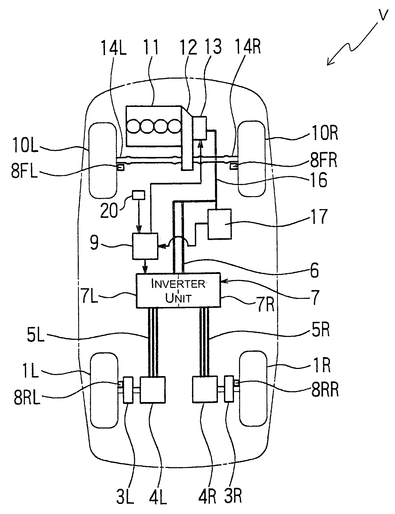
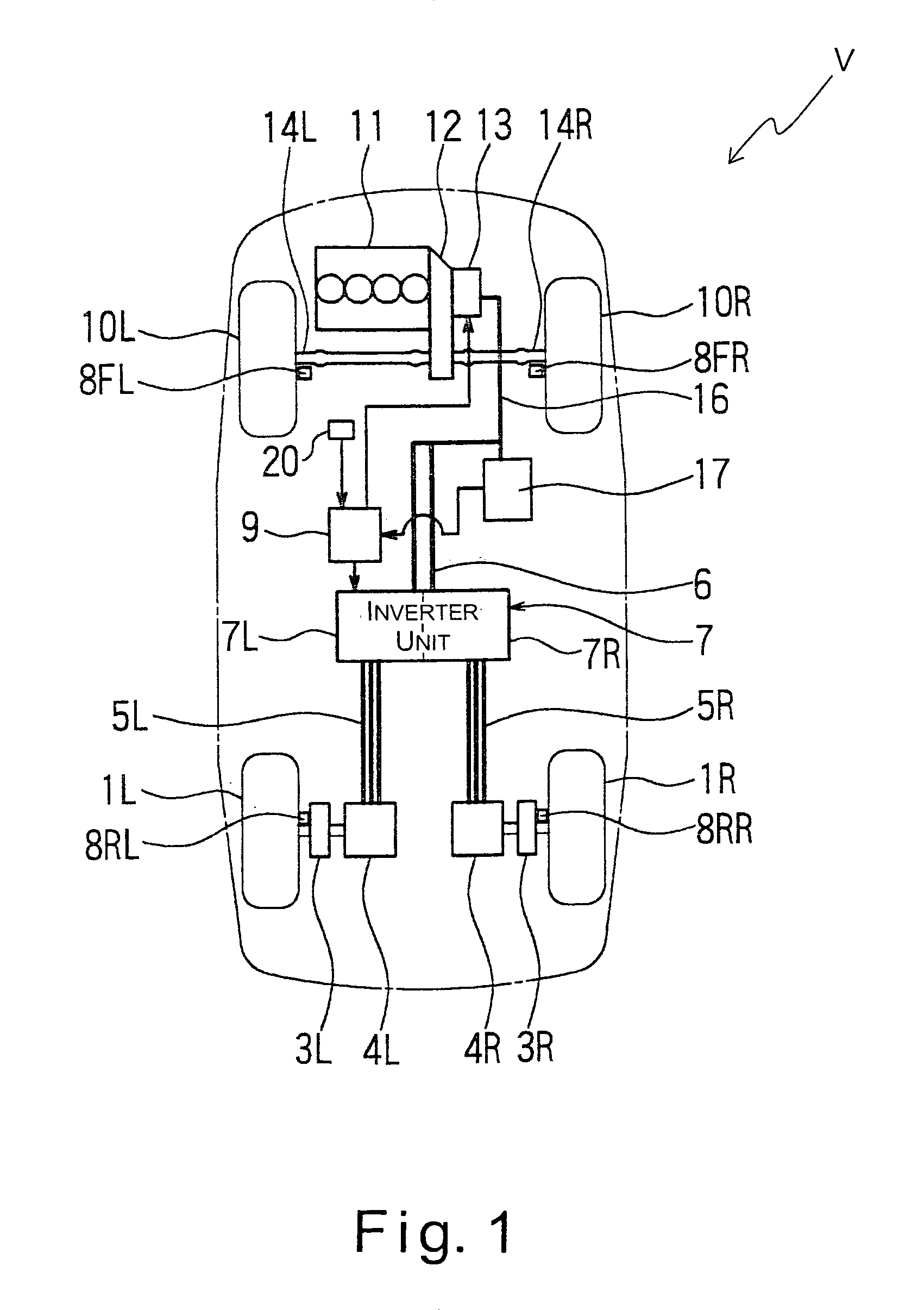
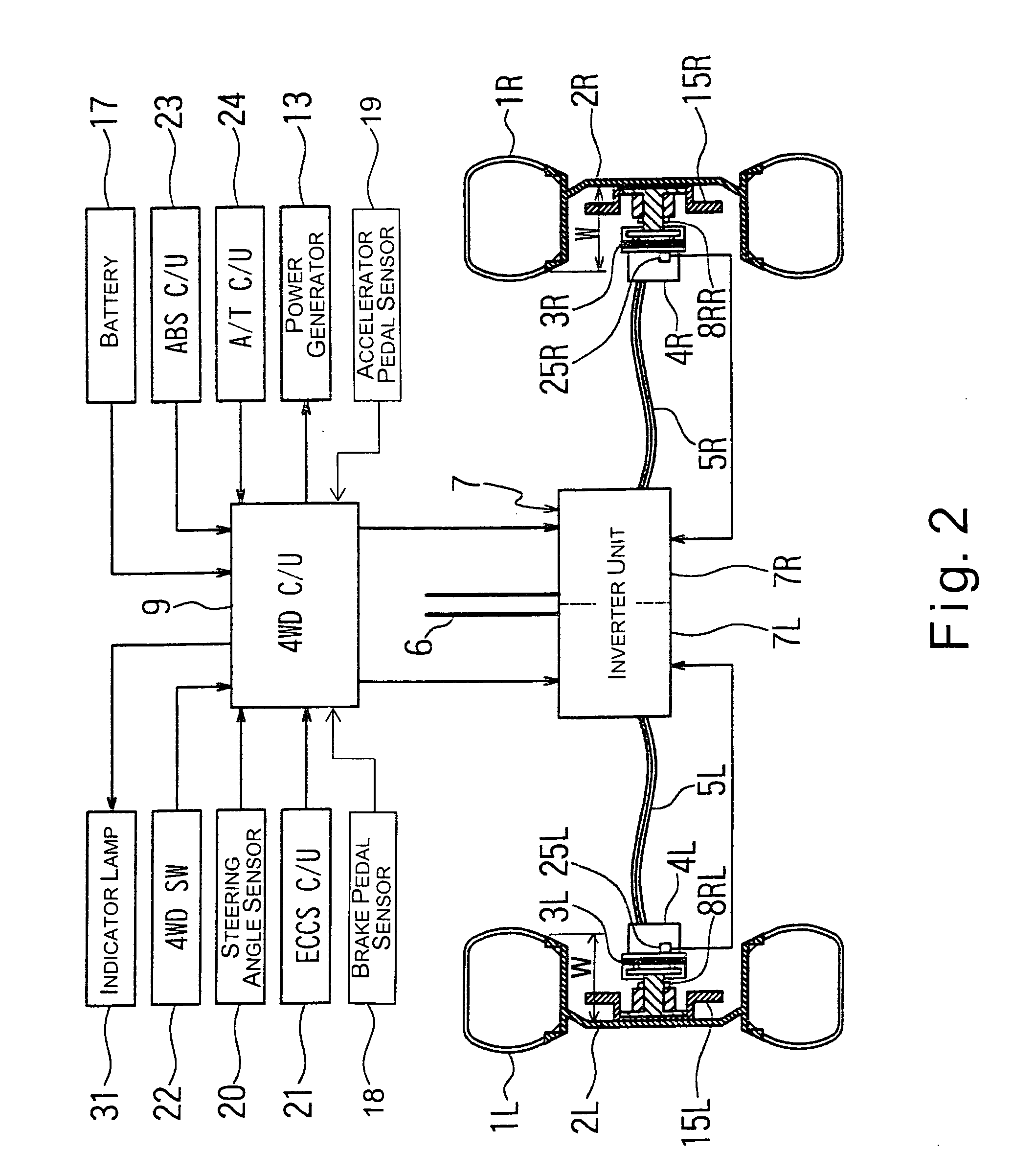
[0097]FIG. 10 is a simplified schematic view of an overall drive control system of the hybrid 4WD vehicle V equipped with the drive apparatus of the third embodiment. FIG. 11 is a schematic view of the drive apparatus illustrated in FIG. 10 including a drive control system of a left rear wheel 1L and a right rear wheel 1R of the hy...


PUM


Abstract

A drive apparatus basically comprises left and right drive units each including at least a reduction gear, an electric motor without a permanent magnet, and a brake disc. Each of the left and right drive units is housed substantially within a rim of each of rear wheels which are driven wheels. A 4WD control unit is configured to control a pair of inverters to separately drive the electric motors when a vehicle speed is in a range between a standing start speed and a prescribed vehicle speed, and to stop driving the electric motors when the vehicle speed is equal to or greater than the prescribed vehicle speed to place the rear wheels in a driven state. Accordingly, a friction loss due to a cogging torque encountered in a conventional permanent magnet-type motor is eliminated, and a lightweight drive apparatus is obtained. Fuel efficiently is accordingly improved.

Description

BACKGROUND OF THE INVENTION[0001]1. Field of the Invention[0002]The present invention relates to a drive apparatus for a vehicle in which one pair of front or rear wheels are driven by a vehicle power train and the other pair of the front or rear wheels are driven by a pair of electric motors coupled to the other pair of the front or rear wheels.[0003]2. Background Information[0004]In a conventional four-wheel drive vehicle that only has an engine as a power train, a space for accommodating a propeller shaft extending from a transmission in the front of the vehicle to the rear wheels is required. Therefore, in the conventional four-wheel drive vehicle, a propeller shaft tunnel is provided at a substantially widthwise center portion of a floor of the vehicle under the rear seats. In such a case, the floor is not level, and thus, comfort for the passengers is reduced. Also, another type of conventional four-wheel drive vehicle includes an arrangement in which the driven wheels are dis...

Claims


Application Information

Patent Timeline
Patent Type & Authority Patents(United States)
IPC IPC(8): B60K1/00B60K6/26B60K6/40B60K6/44B60K6/52B60K6/54B60K7/00B60K17/04B60K17/356B60L9/18B60L50/16B60W10/08B60W10/18B60W20/00
CPCB60K6/26B60K6/40B60K6/44B60K6/52B60K6/54B60K17/356B60W10/08B60K6/36Y10S903/906B60K7/0007B60K17/043B60T2270/603Y02T10/52Y02T10/623Y02T10/6265Y02T10/40Y02T10/62
Inventor HATSUDA, TADAYUKINIIKUNI, TETSUYATANIMOTO, TSUTOMU
Owner NISSAN MOTOR CO LTD
Why Eureka
Try Eureka