Automated induction systems and methods for mail and/or other objects

a technology of induction system and mail, applied in the field of automatic induction system and methods for mail and/or other objects, can solve the problems of imposing a set of repetitive motions, requiring substantial manual loading and tending of operators, and requiring substantial manual processing

Active Publication Date: 2007-03-27
NORTHROP GRUMMAN SYST CORP
View PDF87 Cites 38 Cited by
  • Summary
  • Abstract
  • Description
  • Claims
  • Application Information

AI Technical Summary

Benefits of technology

[0018]Various embodiments of the present invention can significantly improve upon existing systems and methods. In some preferred embodiments of the present invention, one or more of the above and / or other problems with existing systems can be overcome.
[0019]The preferred embodiments enable the automatic loading of prepared mail in carriers onto mail processing systems. The process of automatic loading can reduce the requirements on operators—such as, e.g., enabling one operator to tend multiple feeders or systems. The accuracy, repeatability and / or delivery speed of the preferred embodiments can support higher throughput than was available with prior systems. In preferred embodiments, the system can still be run manually and can still retain full functionality for operators to even manually move a paddle during the process. In various embodiments, a variety of configurations and indexing means can be used to provide the desired paddle movements, such as, e.g., ball screws, slide mechanisms, belt drives and / or any other appropriate drive mechanisms.

Problems solved by technology

While the USPS processes approximately 200 billion pieces of mail per year, the mail that is processed requires substantial manual loading and tending by operators.
This manual process involves a substantial amount of demanding labor and imposes a set of repetitive motions on the operators performing the loading.
The burden placed upon the operators who feed and / or operate the systems, thus, continues to increase.
Otherwise, the angle of orientation relative to the paddle may vary too substantially.
As a result, the variation in orientation angle will likely cause a decrease in throughput, an increase in multi-feeds, an increase in damage and / or other problems.

Method used


Image

  • Automated induction systems and methods for mail and/or other objects
  • Automated induction systems and methods for mail and/or other objects
  • Automated induction systems and methods for mail and/or other objects

Examples


Embodiment Construction

[0047]While the present invention may be embodied in many different forms, a number of illustrative embodiments are described herein with the understanding that the present disclosure is to be considered as providing examples of various principles of the invention and such examples are not intended to limit the invention to preferred embodiments described herein and / or illustrated herein.

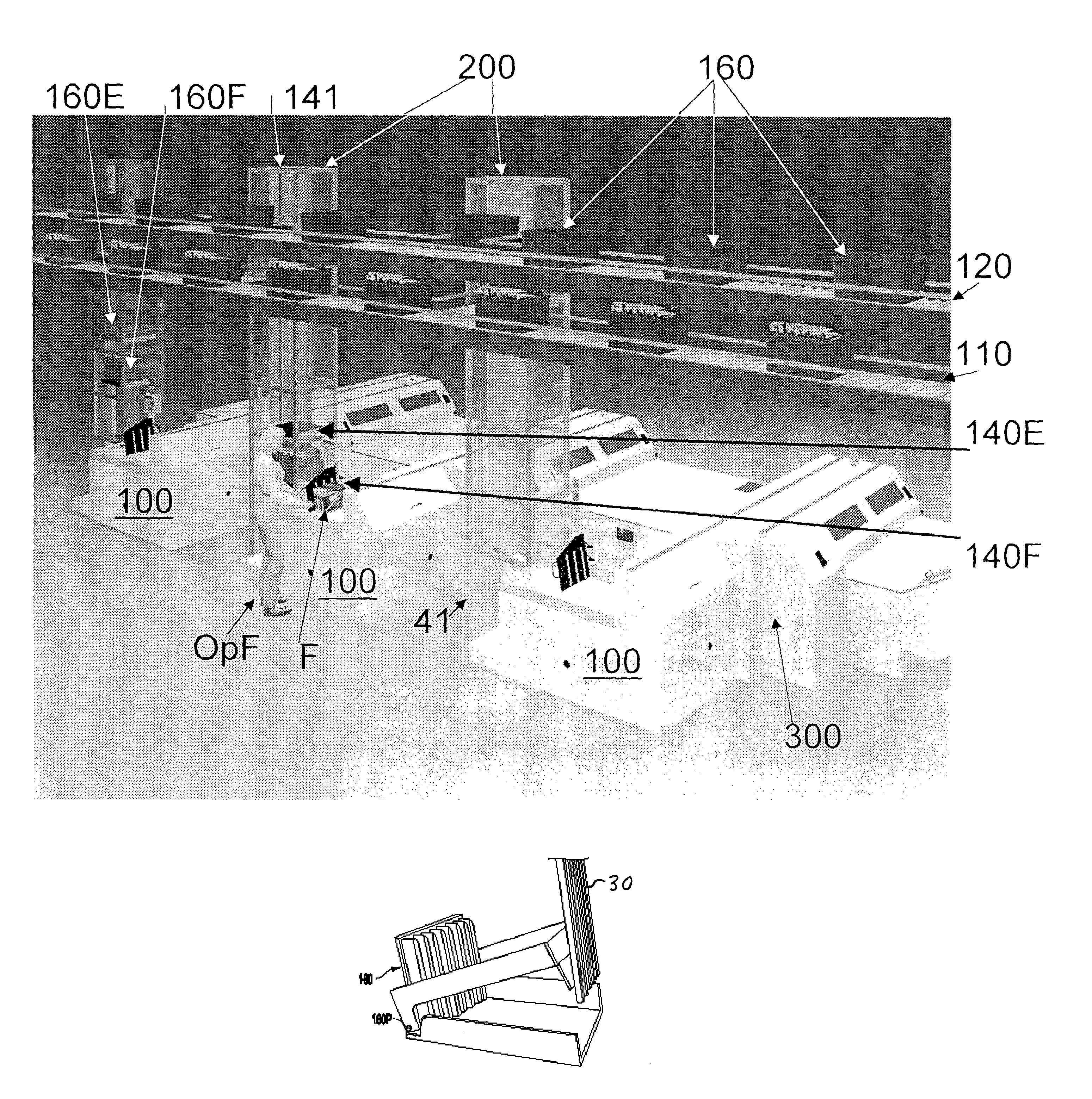
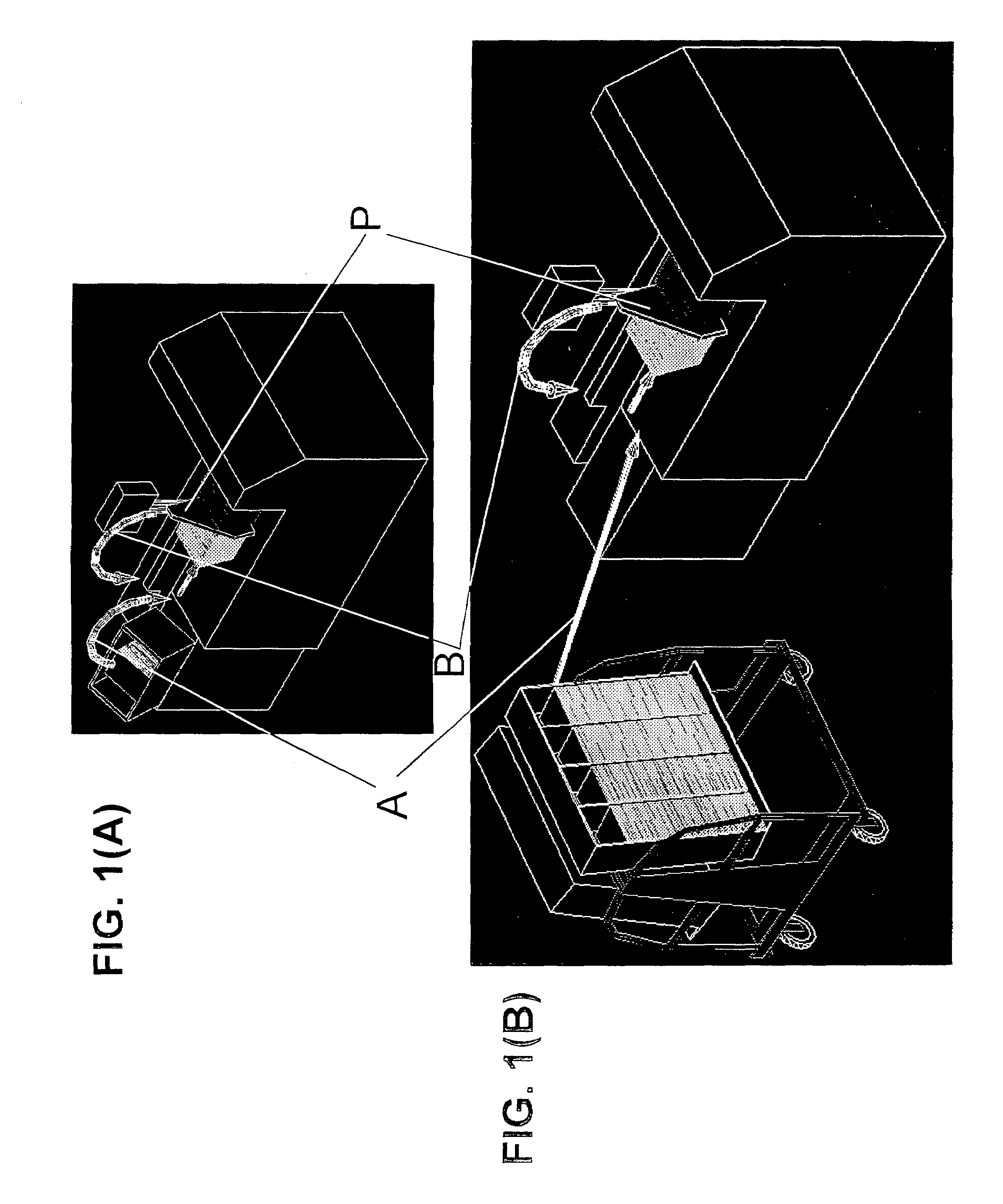
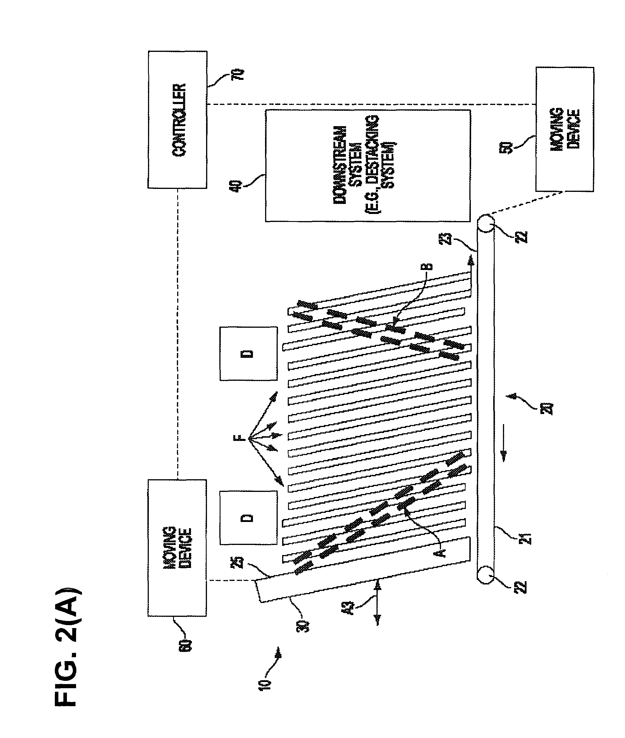
[0048]The preferred embodiments can provide, among other things, a substantially or entirely automated system for use in the processing of thin objects (including, e.g., three-dimensional objects having a size in first dimension that is substantially smaller than sizes in second and third dimensions). While the preferred embodiments can be used to process mail (including, for example, flats, envelopes, letters, postcards and / or other mail), and the most preferred embodiments can be used to process mail flats, various embodiments can also or can alternatively be used to process other thin objects, su...


PUM

PropertyMeasurementUnit
angleaaaaaaaaaa
angleaaaaaaaaaa
angleaaaaaaaaaa

Abstract

In some embodiments, a system for automated loading of a side-by-side stack of thin objects to a feeder is provided. The system can include, e.g.: a) a transporter having a transport surface upon which a side-by-side stack of thin objects can be conveyed; b) a carrier, configured to carry a side-by-side stack of thin objects, over the transport surface; c) a pusher over the transport surface; d) the pusher and the carrier being movable relative to one another between a first position in which the pusher is inside the carrier behind a side-by-side stack of thin objects on the carrier and a second position in which the pusher is laterally displaced from the carrier, such that the side-by-side stack of thin objects on the carrier is laterally slid off of the carrier by the pusher.

Description

[0001]The present application claims priority to Provisional Application Ser. No. 60 / 469,828, filed on May 13, 2003, entitled Enhanced Object-Feeder Pre-Processing System and is a continuation-in-part of Non-Provisional application Ser. No. 10 / 400,522, filed on Mar. 28, 2003, entitled Stack Correction System And Method, the disclosures of which are both incorporated herein by reference in their entireties.BACKGROUND[0002]1. Field of the Invention[0003]The present invention relates generally to, among other things, systems for handling mail (including, e.g., flats, envelopes, letters, postcards and / or other mail) and / or other objects, and certain preferred embodiments relate, more particularly, to automated systems for pre-processing mail flats handled by mail flats sorting systems.[0004]2. Background Discussion[0005]The following discussion is based on the inventors' knowledge and should not be construed as admissions of knowledge in the prior art.[0006]Currently, a variety of syste...

Claims


Application Information

Patent Timeline
Patent Type & Authority Patents(United States)
IPC IPC(8): B65H5/00B07C1/02B07C5/00B42F17/00B43MB65HB65H5/16G06F17/00
CPCB07C1/025B65H1/025B65H1/30B65H2301/42268B65H2301/422542
Inventor HILLERICH, JR., THOMAS A.NEEBE, MARK T.
Owner NORTHROP GRUMMAN SYST CORP
Why Eureka
Try Eureka