Electric manual machine tool driven by an electric motor

a technology of electric motors and electric brushes, which is applied in the direction of mechanical energy handling, drilling pipes, rotary drilling, etc., can solve the problems of prolonged light wear and achieves the effects of prolonging the service life of applicable electrical motors, improving efficiency, and reducing wear and tear of carbon brushes and commutators

Inactive Publication Date: 2007-03-27
ROBERT BOSCH GMBH
View PDF16 Cites 40 Cited by
  • Summary
  • Abstract
  • Description
  • Claims
  • Application Information

AI Technical Summary

Benefits of technology

[0004]The present invention has the advantage that even at extremely high rpm the commutator does not become perceptibly performed and consequences assures a low-spark contact with the carbon brushes. As a result, wear of both the carbon brushes and the commutator is slight, and the service life of the applicable electrical motor is prolonged. Its efficiency is improved, since more electrical power is converted into work and less into heat. Furthermore, because of the lesser amount of arcing, interference in the radio wave range is less, and interference suppression for the hand power tool is simplified or can be dispensed with.

Problems solved by technology

As a result, wear of both the carbon brushes and the commutator is slight, and the service life of the applicable electrical motor is prolonged.

Method used


Image

  • Electric manual machine tool driven by an electric motor
  • Electric manual machine tool driven by an electric motor
  • Electric manual machine tool driven by an electric motor

Examples


Embodiment Construction

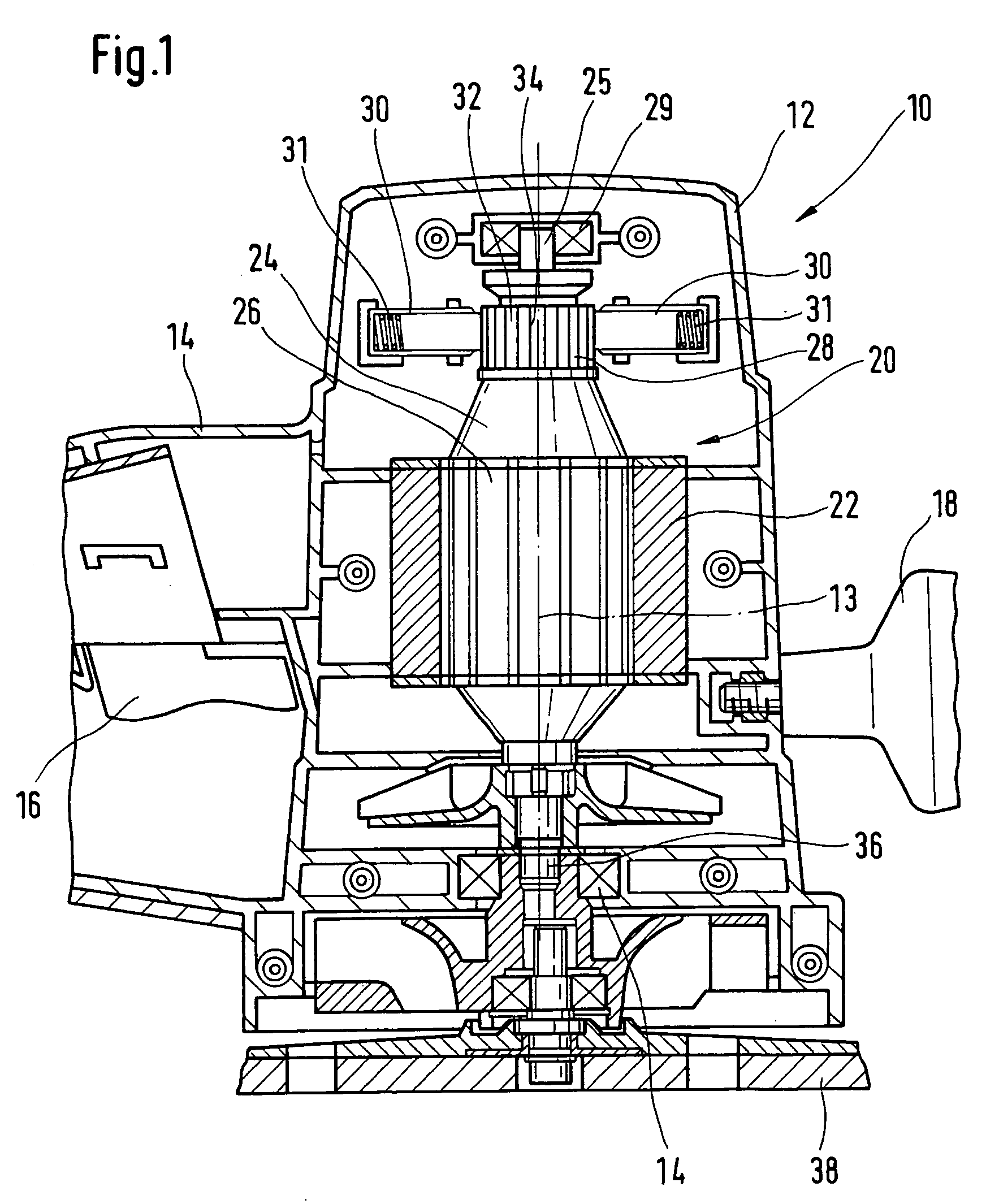
[0025]FIG. 1 shows a longitudinal section through a hand power tool 10, designed as an eccentric wiper, whose stepped-cylindrical housing 12 has a vertically extending longitudinal axis 13 from which a main handle 14 extends essentially vertically radially outward, and an extra handle 18 extends in the opposite direction, that is, toward the front. On the underside of the main handle 14, there is a button 16 of a switch, not identified by reference numeral, that is provided for turning the hand power tool drive 10 on and off.

[0026]Centrally in the housing 20 or relative to the longitudinal axis 13, an electric motor 20 is provided, whose stator 22 is embraced without play by the housing 12 and fixed, and whose central rotor 24 comprises a central rotor shaft 25 that is equipped with radially outward-extending rotor blades. The rotor blades 26 are penetrated by an electrical wire winding, not identified by reference numeral, which is electrically connected to a commutator 28 in a kno...


PUM


Abstract

A hand power tool that is driven via an electric motor (20), the electric motor (20) having a commutator (28) which is formed of disklike annular segments or laminations (32), is made more secure against contact spark development by providing that at least one of the laminations (32) has at least one central recess (42, 44, 46).

Description

BACKGROUND OF THE INVENTION[0001]The invention is based on a hand power tool.[0002]From European Patent Disclosure EP 350 855, a commutator for a universal motor is known, of the kind also provided for hand power tools. Its laminations have the outer contour of a low rectangle whose short sides have U-shaped openings into which an annular armature that bundles the laminations together in ringlike fashion can be placed. The laminations are also shaped in the form of bars and, at the operating speed of approximately 3000 rpm of the electric motor that carries the commutator, they are subjected to relatively strong forces that bend the individual laminations outward and cause the commutator, on its outside oriented toward the carbon brushes, not to have a flat, cylindrical contour but rather to have the tendency of having a curved convex contour. As a result, the contact area between the arched outside of the commutator and the flat carbon brushes is reduced considerably, resulting in ...

Claims


Application Information

Patent Timeline
Patent Type & Authority Patents(United States)
IPC IPC(8): H02K9/00H01R39/00H01R39/14H02K9/06H01R39/04H01R39/54H02K7/14H02K13/00H02K13/10
CPCH01R39/54H02K13/105H02K13/006H02K7/145H01R39/04H02K9/06H01R43/06H02K7/00H02K9/28
Inventor LAMPRECHT, JUSTUS
Owner ROBERT BOSCH GMBH
Why Eureka
Try Eureka