
Vital signs monitoring system for animals

Inactive Publication Date: 2007-03-27
HIXSON TOM
View PDF4 Cites 19 Cited by
  • Summary
  • Abstract
  • Description
  • Claims
  • Application Information

AI Technical Summary

Benefits of technology

[0016]Finally, it is a general object of the invention to provide improved elements and arrangements thereof in an apparatus for the purposes described which is inexpensive, dependable and fully effective in accomplishing its intended purposes.

Problems solved by technology

A particular problem in caring for livestock, particularly livestock maintained in large herds in corrals, cattle pens and feed lots, is the detection of a sick animal at an early stage of illness.
More importantly, viruses contracted by the animal will spread and multiply in the animal's body so quickly, that by the time the first symptoms appear, it is too late for medication and ultimately the animal will die because of lack of early detection.
By this time, the sick animal has exposed other animals in the close proximity of the herd possibly spreading the disease to others, with the result being a substantial financial loss for the owners of the herd.
And more importantly in today's animal health, viruses contracted by the animal will spread and multiply in the animal's body so quickly, that by the time the first symptom appears, it is too late for the medication and ultimately the animal will die because of lack of early detection.
This early detection can only be accomplished by measuring the animal's fever.
The described device, although useful in circumstances such as those for which the present invention is designed, requires an uneconomical, large amount of power because it is always powered up and active when an individual signal such as the internal temperature signal is present.
It must be supplied with batteries which, due to the relatively large power consumption of the device, have to be replaced fairly frequently.
The replacement of these batteries is a time consuming and expensive undertaking, especially for very large herds.

Method used


Image

  • Vital signs monitoring system for animals
  • Vital signs monitoring system for animals
  • Vital signs monitoring system for animals

Examples


Embodiment Construction

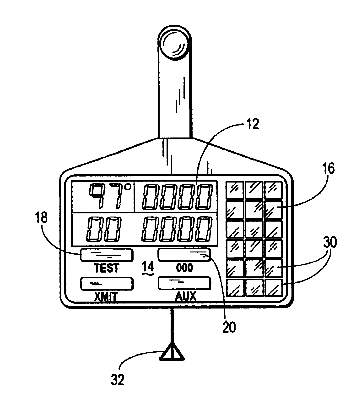
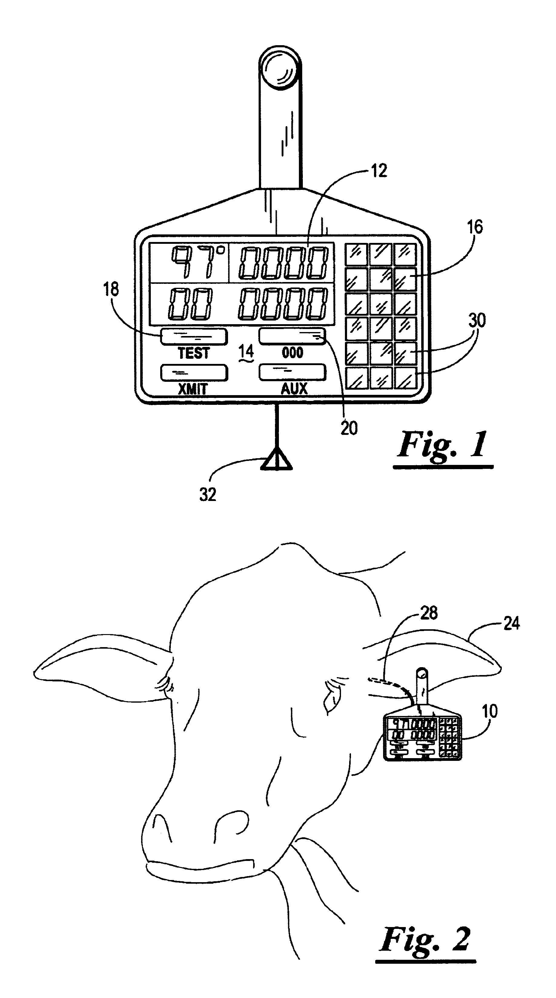
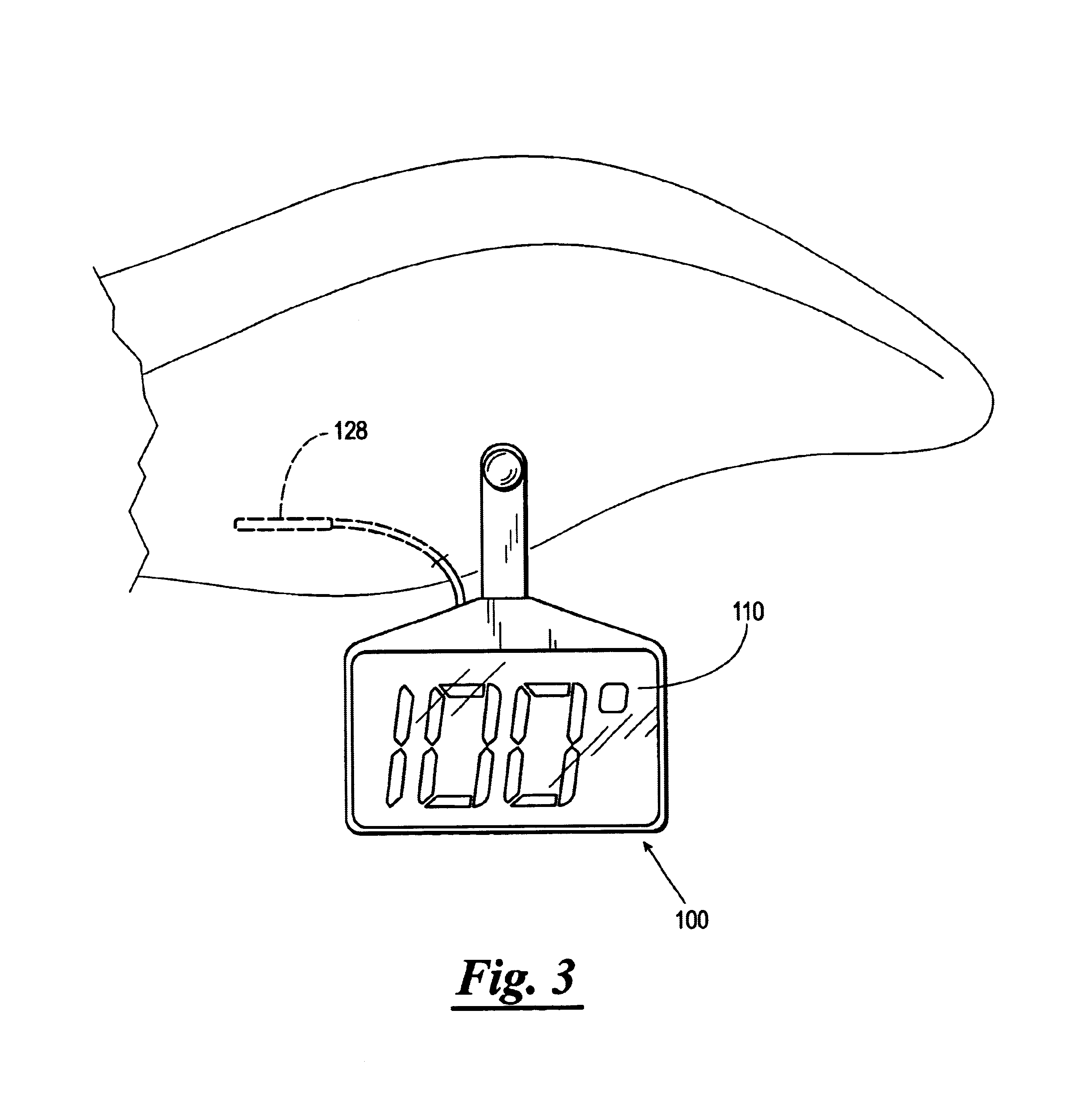
[0023]Referring now to FIGS. 1-4, the animal monitoring device of the invention, generally indicated by the numeral 10, is shown. The device 10 has three main components; the display panel 12, the keypad 14, and the solar cell panel 16.

[0024]The display panel 12 may be an LCD display capable of displaying at least two arabic numerals. The display panel 12 may indicate temperature, or may provides data related to other vital signs. As discussed above, it is often useful in the maintenance of livestock to detect when one or more animals in the herd have developed an illness in order to treat and / or remove them from the herd and reduce the possibility of contagion. One way of determining when an animal is ill is the presence of a fever which will appear in the animal after initial exposure to the virus or bacteria causing the infection.

[0025]For instance, if the livestock is cattle, an internal temperature of 40.degree. C. or 104.degree. F. indicates a fever and illness. For relatively...


PUM


Abstract

A self powered monitoring device for monitoring an animal's temperature and other vital signs. The device may be mounted in the animal's ear, under the animals skin, or in any location which can be used to generate a reliable indication of the animals temperature and other vital signs. The temperature probe for the device is inserted subcutaneously and thermally and / or electrically connected to the housing of the device. Power for the device is provided by a miniature array of solar cells, the power from the solar cells being used to drive digital circuitry which processes signals from the various probes used to gather data concerning the animal's vital signs. The size of the array is chosen to be commensurate with the number of vital signs monitored, with the amount of sunlight, density of herd, and other factors being considered to ensure sufficient power for the device.

Description

BACKGROUND OF THE INVENTION[0001]The present invention relates to animal husbandry. More particularly, the invention relates to a self powered monitoring device for measuring and displaying an animal's temperature and other vital signs.Statement of the Prior Art[0002]With the proliferation of modem digital electronics, many of the problems of caring for large herds of livestock have been addressed. A particular problem in caring for livestock, particularly livestock maintained in large herds in corrals, cattle pens and feed lots, is the detection of a sick animal at an early stage of illness. In the past, detection was generally accomplished by visual observation of the herd, in which case the ability and attentiveness of the individual observing the herd was important as sick animals at an early stage of illness can have very minor symptoms, not easily discerned by an inexperienced or inattentive individual. More importantly, viruses contracted by the animal will spread and multipl...

Claims


Application Information

Patent Timeline
IPC IPC(8): G08B23/00A61B5/00
CPCA61B5/01Y10S128/903A61B2560/0214A61B2503/40
Inventor HIXSON, TOM
Owner HIXSON TOM
Learn More