Driving apparatus and method for active matrix organic light emitting display

a technology of organic light and driving apparatus, applied in the direction of instruments, computing, electric digital data processing, etc., can solve the problems of inability to increase resolution, the product size of pmoled is still limited to about 5 inches, and the cost and technical threshold for pmoled fabrication is lower, so as to improve the image uniformity of amoled panels and reduce the cost of fabrication

Active Publication Date: 2007-03-27
WINTEK CORP
View PDF11 Cites 7 Cited by
  • Summary
  • Abstract
  • Description
  • Claims
  • Application Information

AI Technical Summary

Benefits of technology

[0012]Therefore the primary object of the invention is to resolve the aforesaid disadvantages and to overcome the drawbacks of the prior art. The invention may be adopted for LTPS-TFT AMOLED devices to improve image uniformity of AMOLED panels. Moreover, the driving method employed by the invention is less complicated technical wise. And the scan driving IC and data driving IC employed in the conventional PMOLED may be used. Thus fabrication cost may be reduced.
[0013]In order to achieve the foregoing object, the driving element provided by the invention includes a writing element, an auto-zero element, a driving element, a switching element and a storage element. The apparatus employs an auto-zero mechanism to compensate variations of threshold voltage of each driving element to improve image uniformity. Compared with the pixel circuit that uses 4T2C, the invention saves one capacitor, and can increase the aperture ratio of the pixel. Complexity of the driving method also may be reduced.

Problems solved by technology

Although the cost and technical threshold for fabrication of the PMOLED are lower, the products of PMOLED are still limited to about 5 inches in size and the resolution cannot increase due to the constraint of the driving method.
Thus they are restricted in the market of low resolution and small dimension.
The main differences between LTPS TFT and a-Si TFT are in electricity and manufacturing complexity.
LTPS TFT has a higher carrier-mobility which means that TFT can better provide sufficient current, but its manufacturing process is more complicated.
This phenomenon causes the ill gray level on OLED display panel and severely damages image uniformity of the panel.
The driving method becomes very complicated.
Hence it requires non-standard scan driving IC and data driving IC, and fabrication cost is higher.

Method used


Image

  • Driving apparatus and method for active matrix organic light emitting display
  • Driving apparatus and method for active matrix organic light emitting display
  • Driving apparatus and method for active matrix organic light emitting display

Examples


Embodiment Construction

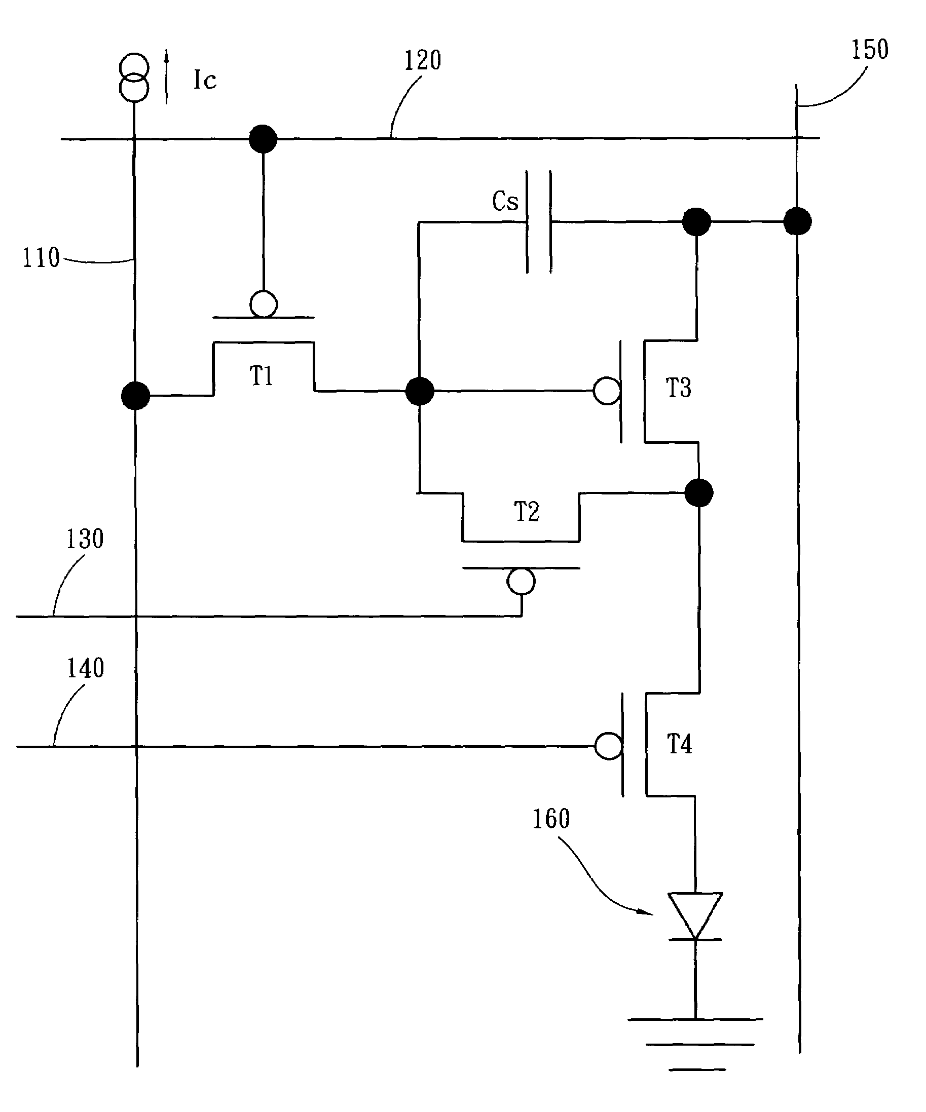
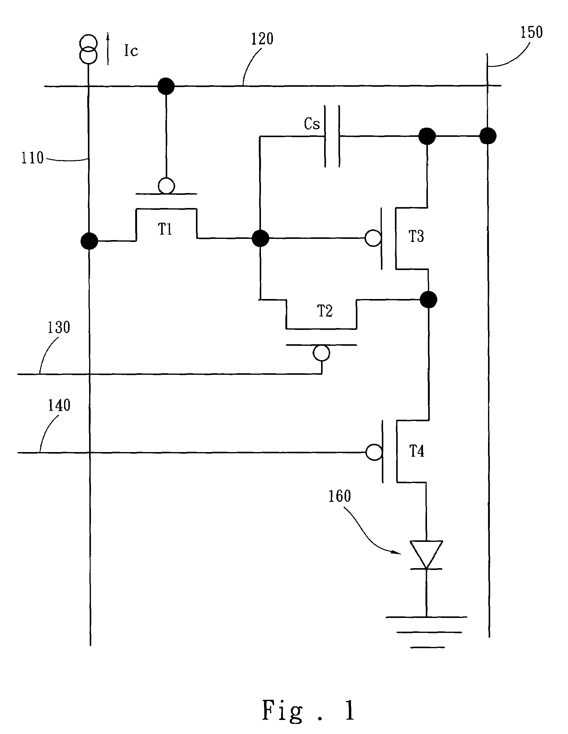
[0019]Referring to FIG. 1, the driving apparatus of the invention includes:

[0020]a data line 110, a scan line 120, an auto-zero control line 130, a display control line 140, a power supply line 150;

[0021]a writing element T1 which has a drain connecting to the data line 110, and a gate connecting to the scan line 120;

[0022]an auto-zero element T2 which has a gate connecting to the auto-zero control line 130;

[0023]a driving element T3 which has a gate connecting to the source of the writing element T1 and a drain connecting to the source of the auto-zero element T2, and a source connecting to the power supply line 150;

[0024]a switching element T4 which has a gate connecting to the display control line 140 and a source connecting to the source of the auto-zero element T2 and the drain of the driving element T3;

[0025]a storage element Cs which has two ends, one end connecting to the source of the driving element T3 and the other end connecting to the juncture of the source of the writi...


PUM


Abstract

A driving apparatus and method for active matrix organic light emitting display includes a writing element, an auto-zero element, a driving element, a switching element and a storage element. The invention employs an auto-zero mechanism to compensate threshold voltage variations of each driving element to improve image uniformity. Data loading is accomplished by charging the storage element with a current. Loading voltage may be modulated by controlling the amount of current and by controlling charging time. The invention saves a capacitor than conventional techniques, and can increase the aperture ratio of pixels and reduce the complexity of driving method.

Description

FIELD OF THE INVENTION[0001]The present invention relates to a driving apparatus and method for active matrix organic light emitting display (AMOLED) and particularly to a driving apparatus and method to improve image uniformity of OLED panels.BACKGROUND OF THE INVENTION[0002]The methods for driving OLED can be divided into passive matrix OLED (PMOLED) and active matrix OLED (AMOLED). The AMOLED uses thin-film transistors (TFTs) and capacitors to store signals for controlling the brightness and gray scale of the OLED. Although the cost and technical threshold for fabrication of the PMOLED are lower, the products of PMOLED are still limited to about 5 inches in size and the resolution cannot increase due to the constraint of the driving method. Thus they are restricted in the market of low resolution and small dimension. To achieve a higher resolution and a larger screen, active driving method must be used. The active driving method uses capacitors to store signals, so that the pixel...

Claims


Application Information

Patent Timeline
Patent Type & Authority Patents(United States)
IPC IPC(8): G09G3/32
CPCG09G3/325G09G3/3233G09G2300/0842G09G2300/0465G09G2300/0819G09G2300/0861G09G2320/043G09G2320/0233
Inventor LO, SHIN-TAI
Owner WINTEK CORP
Why Eureka
Try Eureka