Two-dimensional optical scan system using a counter-rotating disk scanner

a scanning system and disk scanner technology, applied in the field of two-dimensional optical scanning systems, can solve the problems of limited scan resolution of these devices, complex and/or costly scanning systems, and large number of scans, and achieve the effect of significantly reducing the net bow and high speed

Active Publication Date: 2007-03-27
SOLTA MEDICAL
View PDF114 Cites 20 Cited by
  • Summary
  • Abstract
  • Description
  • Claims
  • Application Information

AI Technical Summary

Benefits of technology

[0012]In one implementation, the facets on the scan disks include lenses and the lenses on corresponding facets have approximately the same optical power. Aberrations can be corrected in a number of ways. For example, the lenses can be aspheric, with the asphericity correcting “dynamic” aberrations introduced by rotation of the facets through the optical axis. Furthermore, a separate lens group can correct for optical power and / or aberrations introduced by the facets. One advantage of a design based on counter-rotating scan disks is that corresponding facets can be designed to introduce scan line bows that counteract each other, so the net bow is significantly reduced. Another advantage is that the scan disks can be rotated at high speeds.

Problems solved by technology

As a result, the two-dimensional scanners used in these optical systems can be complex and / or costly.
For example, in the case of large screen HDTV displays that are suitable for projection use in conference rooms, the high screen resolution combined with short frame periods and high screen brightness levels typically results in complex and costly scan systems.
However, the scan resolution of these devices is limited by the limited number of scan facets that can be placed on the scan mechanisms and by the limitations on numerical aperture (NA) imposed by the scanning facet geometries.

Method used


Image

  • Two-dimensional optical scan system using a counter-rotating disk scanner
  • Two-dimensional optical scan system using a counter-rotating disk scanner
  • Two-dimensional optical scan system using a counter-rotating disk scanner

Examples


Embodiment Construction

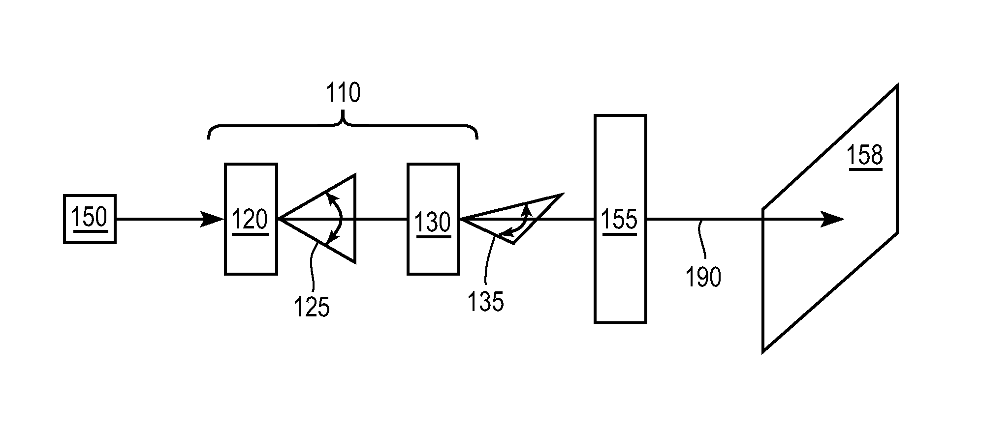
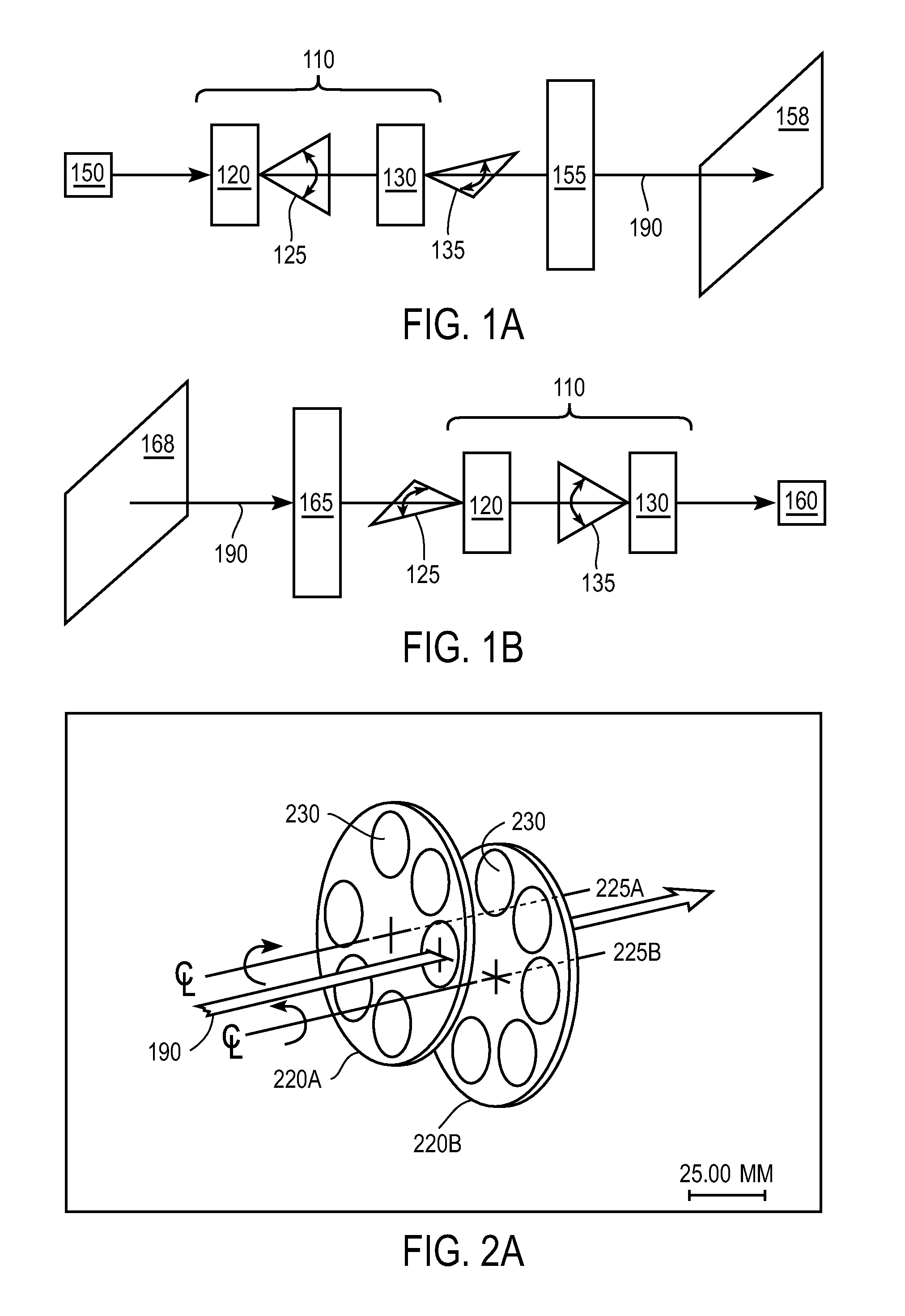
[0029]FIGS. 1A–1B are block diagrams of two optical systems that use a two-dimensional scan system 110 according to the invention. In the display of FIG. 1A, an optical source 150 produces one or more optical beam(s) that are imaged by the imaging system 155 onto a display surface 158. The optical train of this system also includes a two-dimensional scan system 110 that scans the optical beam(s) to produce the displayed image. In the imaging system of FIG. 1B, an exterior scene 168 is imaged by the imaging system 165 onto a detector (or detector array) 160. The two-dimensional scan system 110 scans the field of view of the detector 160 over the scene 168 in order to capture the two-dimensional image.

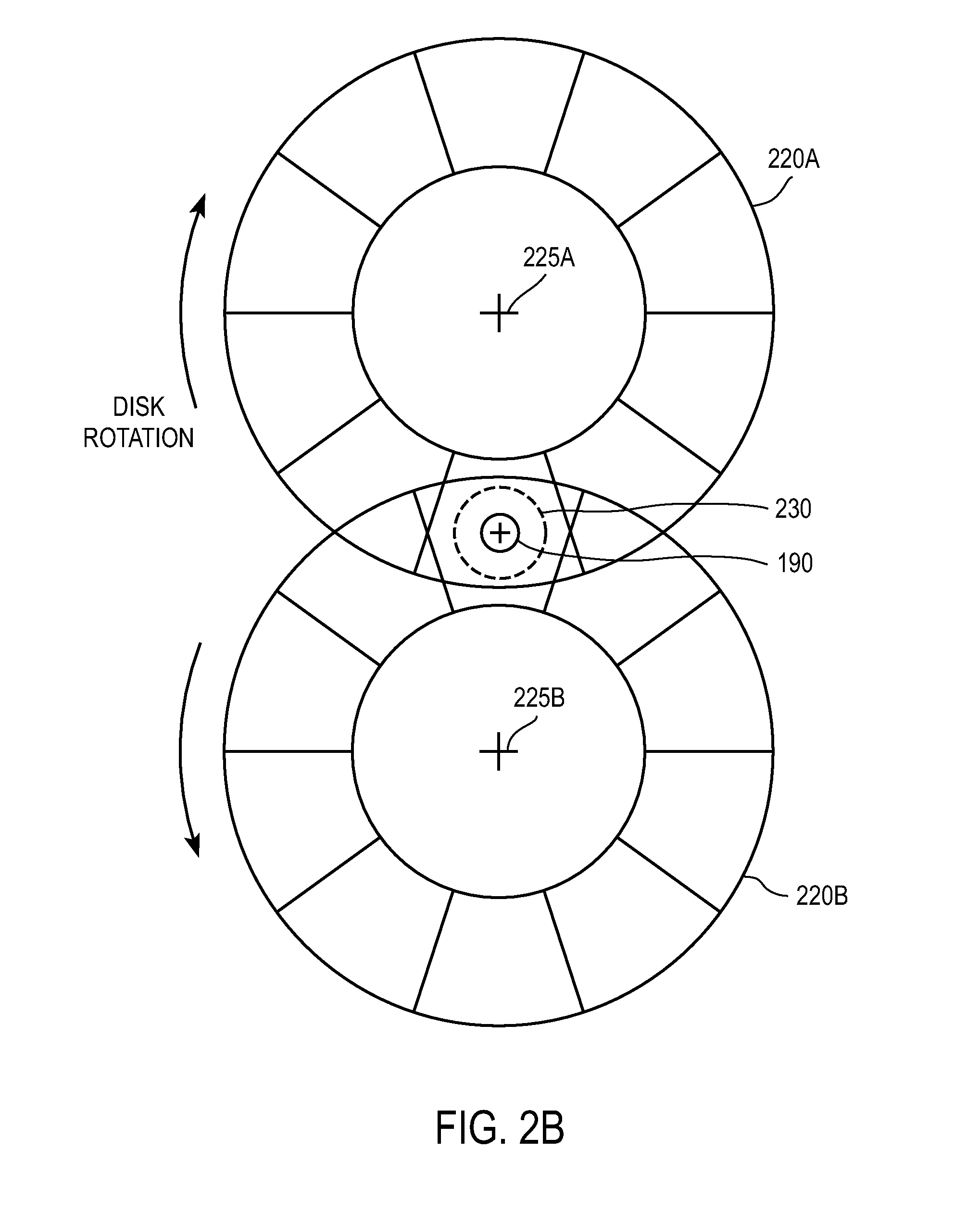
[0030]In both of these examples, the two-dimensional scan system 110 includes a counter-rotating disk scanner 120 and a second scan mechanism 130. The disk scanner 120 implements the scan along one direction 125 and the other scan mechanism 130 implements the scan along a cross direction...


PUM


Abstract

A counter-rotating disk scanner together with another scan mechanism provides two-dimensional optical scanning. The counter-rotating disk scanner includes counter-rotating scan disks that implement the scanning action as they rotate through an optical axis of the system.

Description

CROSS-REFERENCE TO RELATED APPLICATION(S)[0001]This application is a continuation-in-part of U.S. patent application Ser. No. 10 / 750,790, “High Speed, High Efficiency Optical Pattern Generator Using Rotating Optical Elements,” filed Dec. 31, 2003 by Leonard C. DeBenedictis et al. The subject matter of the foregoing is incorporated herein by reference in its entirety.BACKGROUND OF THE INVENTION[0002]1. Field of the Invention[0003]This invention relates generally to two-dimensional optical scanners, such as for use in displays. More particularly, this invention relates to two-dimensional optical scanners that use multi-faceted rotating scan disks.[0004]2. Description of the Related Art[0005]Two-dimensional optical scan systems can be used in a variety of applications. For example, they can be used to scan an optical beam over a specified area in order to generate a two-dimensional display. As another example, they can be used to scan the field of view of a detector (or detector array)...

Claims


Application Information

Patent Timeline
Patent Type & Authority Patents(United States)
IPC IPC(8): G02B26/08G02B26/10G02B26/12
CPCG02B26/0875G03B21/14G02B26/106G02B26/10
Inventor BROOME, BARRY GFRANGINEAS, JR., GEORGEDEBENEDICTIS, LEONARD C
Owner SOLTA MEDICAL
Why Eureka
Try Eureka