Image forming apparatus with transfer belt speed control

a technology of transfer belts and forming apparatuses, applied in electrographic process apparatus, instruments, optics, etc., can solve the problems of increased fabrication costs, difficult to fabricate transfer belts, uneven thickness, etc., and achieve the effect of high quality

Inactive Publication Date: 2007-03-27
RICOH KK
View PDF12 Cites 14 Cited by
  • Summary
  • Abstract
  • Description
  • Claims
  • Application Information

AI Technical Summary

Benefits of technology

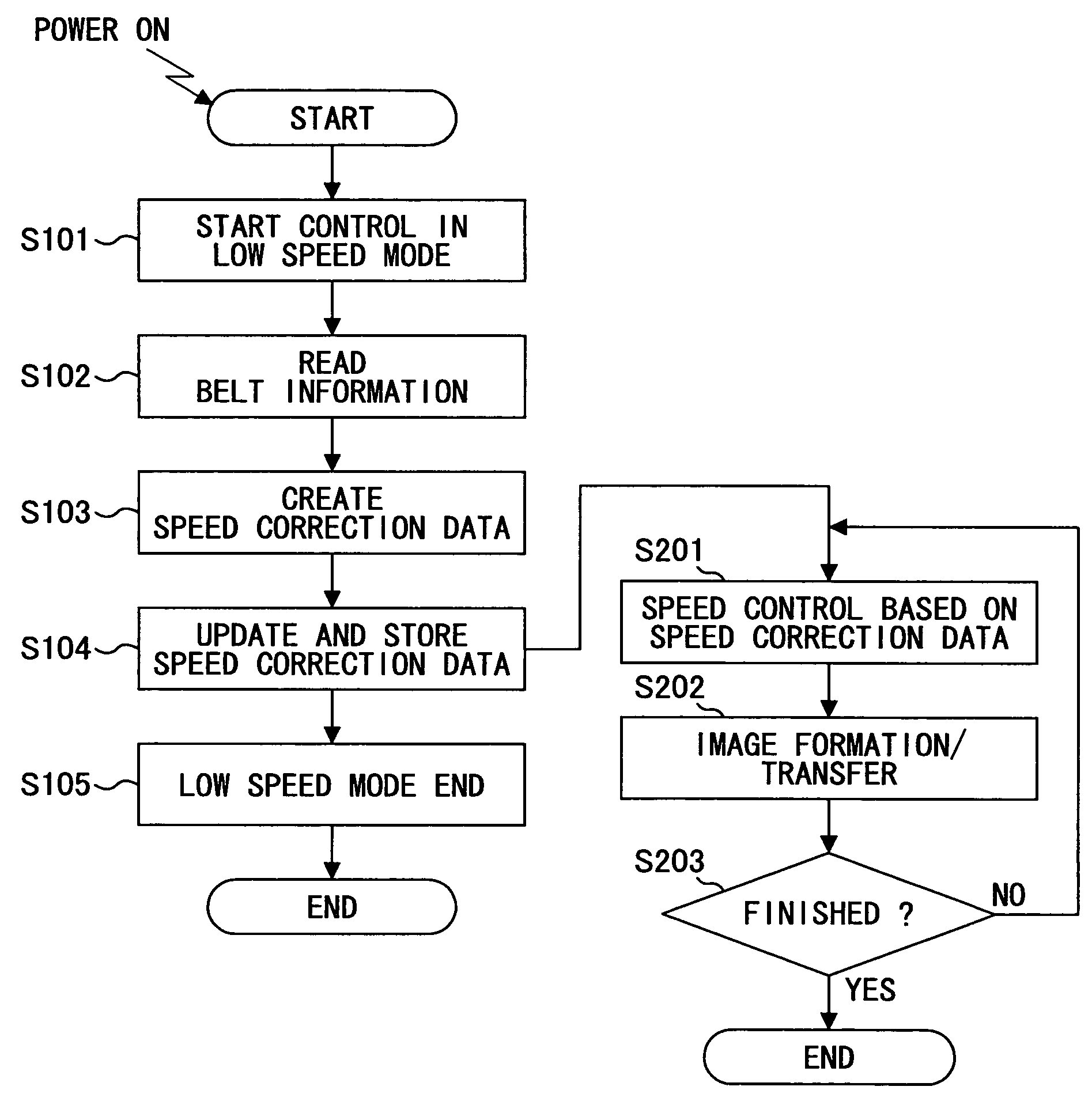
[0045]A specific object of the present invention is to provide an image forming apparatus capable of automatically acquiring data of variation of thickness of a transfer belt newly installed in the image forming apparatus without manual operation of setting the data, and capable of controlling the moving speed of the newly installed transfer belt to be constant based on the acquired data so as to output images of high quality constantly.

Problems solved by technology

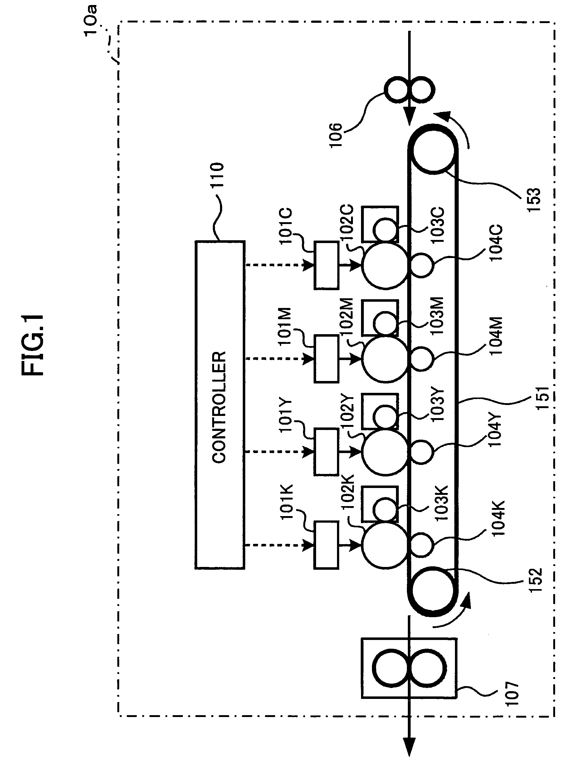
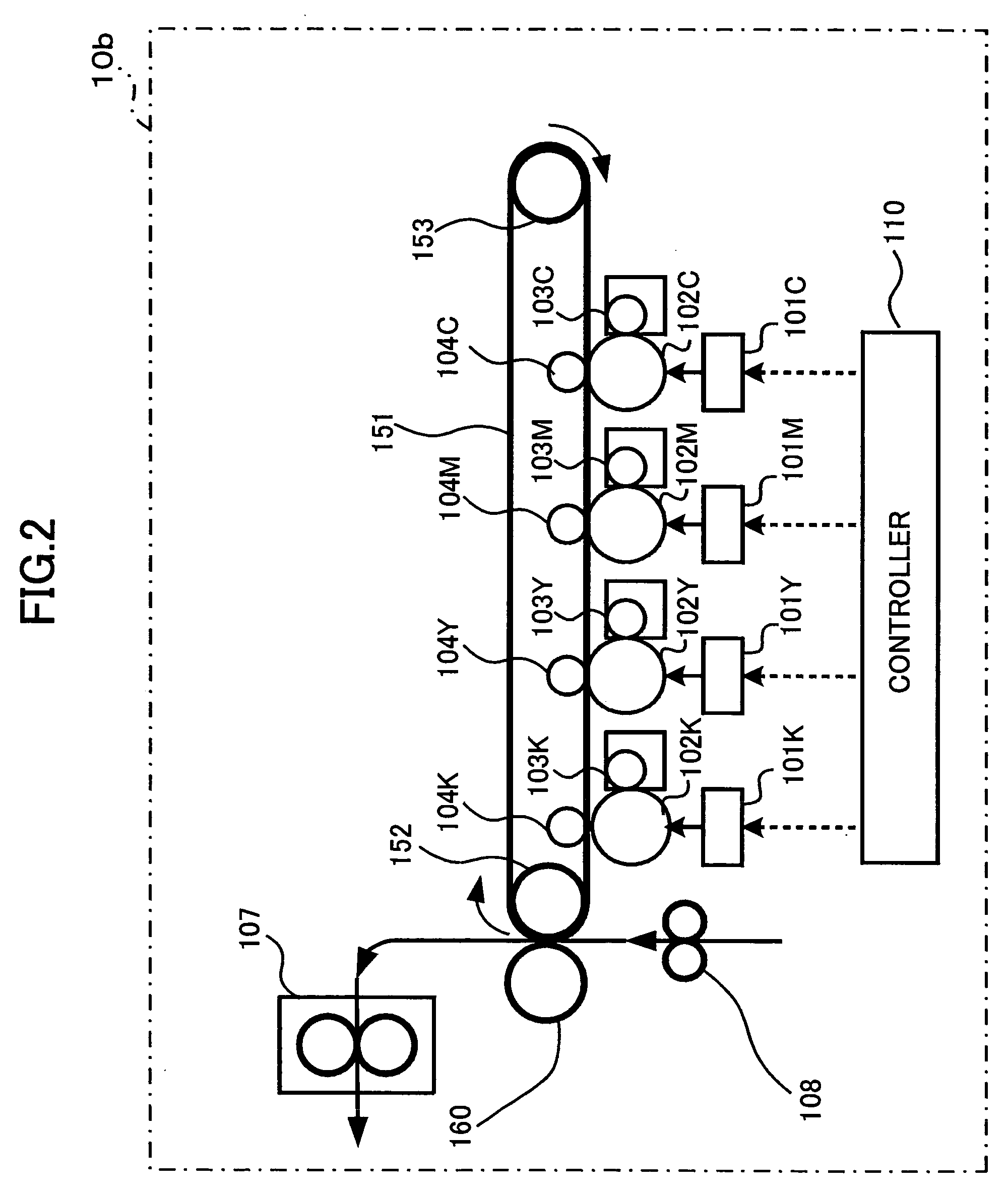
However, because the transfer belt 151 is film-like, that is, it is relatively long, and relatively thin and narrow, it is difficult to fabricate the transfer belt 151 to have a uniform thickness, especially in the longitudinal direction (that is, the rotation direction).
However, in the method disclosed in Japanese Laid-Open Patent Application 6-127037, although it is possible to measure the moving speed of the outer surface of the transfer belt accurately, it is difficult to form the striped pattern on the belt, and this increases the fabrication cost.
Consequently, the apparatus becomes quite expensive.
In the method disclosed in Japanese Laid-Open Patent Application 11-174932, because additional parts like the driven roller, the encoder, and a circuit exclusively used for the feedback control are necessary, the apparatus becomes quite expensive.
However, variations in the thickness of a transfer belt are caused by fluctuations in the fabrication condition of the transfer belt, and different transfer belts have respectively different thickness uncertainties.
Therefore, measured thickness variation of one belt cannot be used for other belts.
This operation is cumbersome, and if the setting is wrong by mistake, expected printing quality cannot be obtained, or the printing quality may be much degraded.

Method used


Image

  • Image forming apparatus with transfer belt speed control
  • Image forming apparatus with transfer belt speed control
  • Image forming apparatus with transfer belt speed control

Examples


Embodiment Construction

[0074]Below, preferred embodiments of the present invention are explained with reference to the accompanying drawings.

[0075]FIG. 3 is a block diagram showing a schematic configuration of a color image forming apparatus 1 according to the present embodiment.

[0076]The color image forming apparatus 1 illustrated in FIG. 1 includes a CPU (Central Processing Unit) 2, a ROM (Read-Only Memory) 3, a RAM (Random Access Memory) 4, a parameter memory 5, an operational panel 6, a motor 7b, a motor controller 7, a motor driving circuit 7a, an I / O unit 8, a counter 9, a plotter 10, an interface 11, and system buses 12.

[0077]The CPU 2 executes control programs stored in the ROM 3, and controls components of the color image forming apparatus while using a working area of the RAM 4.

[0078]The ROM 3 stores the aforesaid control programs for use of the CPU 2, and permanent data referred by the control programs while being executed.

[0079]The RAM 4 provides a working area for the CPU 2 to store temporal ...


PUM


Abstract

An image forming apparatus is disclosed that is capable of automatically acquiring thickness variation data of a transfer belt newly installed in the image forming apparatus without manual operation of setting the thickness variation data, and capable of controlling the moving speed of the newly installed transfer belt to be constant based on the acquired data so as to output images of high quality constantly. The transfer belt includes a belt information mark recorded with information used for creating rotational speed correction data, and the rotational speed control unit includes a storage unit configured to store the rotational speed correction data. A rotational speed control unit is provided that includes a belt information reading unit for reading the belt information mark to obtain the belt information, and a correction data updating unit for updating and storing the rotational speed correction data based on the obtained belt information.

Description

BACKGROUND OF THE INVENTION[0001]1. Field of the Invention[0002]The present invention relates to an image forming apparatus able to be used in a printer, a copier, or a combination of them, and more particularly, to an image forming apparatus in which a target color image is formed by transferring and superposing monochromatic color images on photo conductors to a transfer belt sequentially, and a moving speed of the transfer belt is controlled to be constant so as to suppress color deviation.[0003]2. Description of the Related Art[0004]Among electrophotographic image forming apparatuses, market demand for color image forming apparatuses, such as color printers, color copiers, is rapidly increasing, and especially recently, users are requiring a speed of color image formation comparable to that of monochromatic image formation.[0005]In order to meet this demand, a tandem engine configuration is more and more adopted in the color image forming apparatus. In a color image forming appa...

Claims


Application Information

Patent Timeline
Patent Type & Authority Patents(United States)
IPC IPC(8): G03G15/16G03G21/00G03G15/01G03G21/14
CPCG03G15/0131G03G2215/0158G03G2215/0119
Inventor NISHIZAKI, SHINGO
Owner RICOH KK
Why Eureka
Try Eureka