System and method for thermal monitoring of IC using sampling periods of invariant duration

a technology of invariant duration and thermal monitoring, applied in the field of system and method for thermal monitoring of ic using invariant duration, can solve the problems of introducing significant errors into the measurement of temperature, and the inability to determine the true temperature of the above-mentioned method of temperature sensing

Inactive Publication Date: 2007-03-27
INT BUSINESS MASCH CORP
View PDF7 Cites 15 Cited by
  • Summary
  • Abstract
  • Description
  • Claims
  • Application Information

AI Technical Summary

Problems solved by technology

It has been found that the above variations in processor reference frequency can introduce significant error into the measurement of temperature.
Thus, a user of the above prior art approach for temperature sensing could not be sure that the true temperature was being determined.
This uncertainty has made it necessary to heavily guardband the “acceptable” temperature range of the hardware or software that is relying on the temperature sensor readings for its proper operation.

Method used


Image

  • System and method for thermal monitoring of IC using sampling periods of invariant duration
  • System and method for thermal monitoring of IC using sampling periods of invariant duration
  • System and method for thermal monitoring of IC using sampling periods of invariant duration

Examples


Embodiment Construction

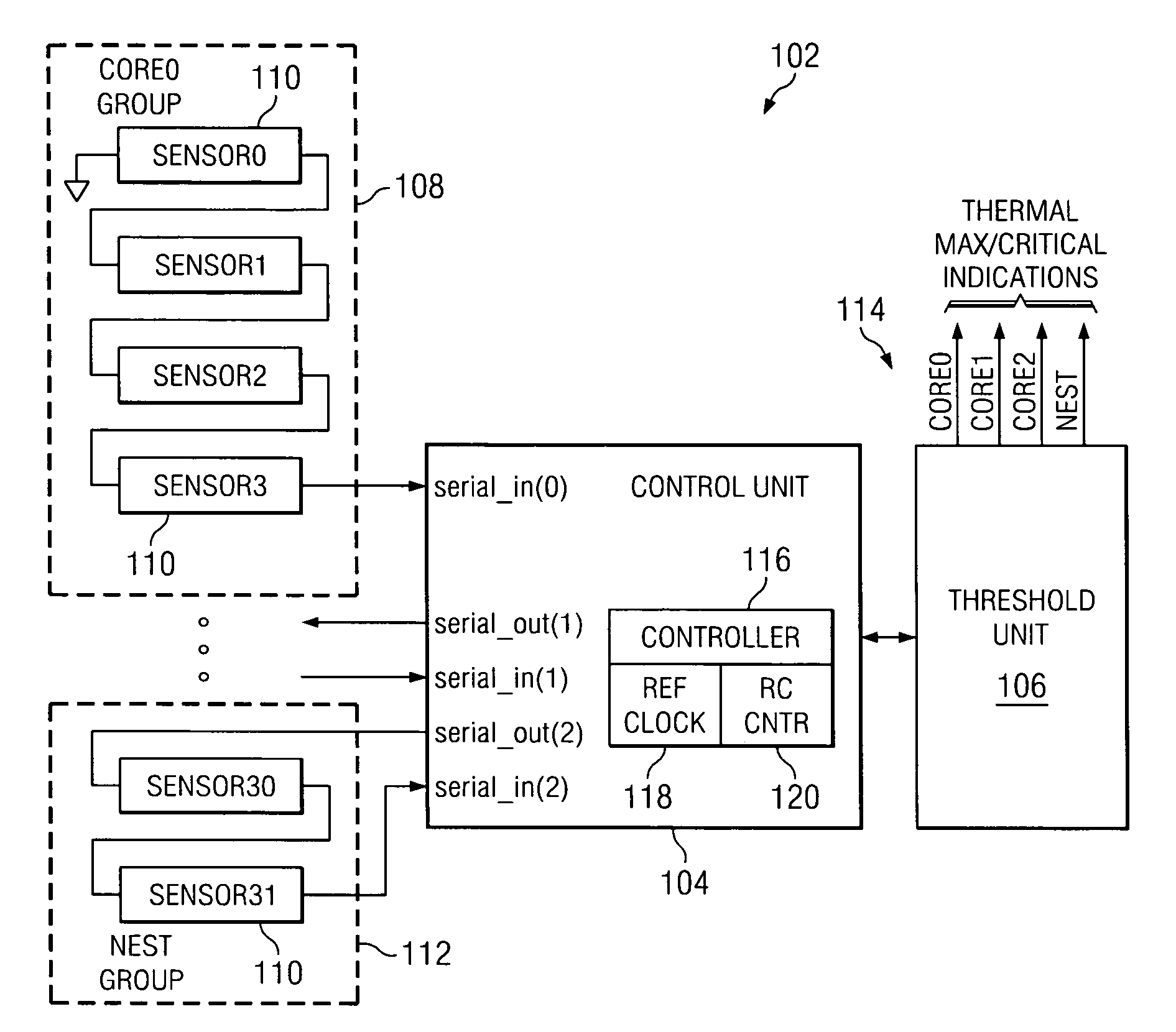
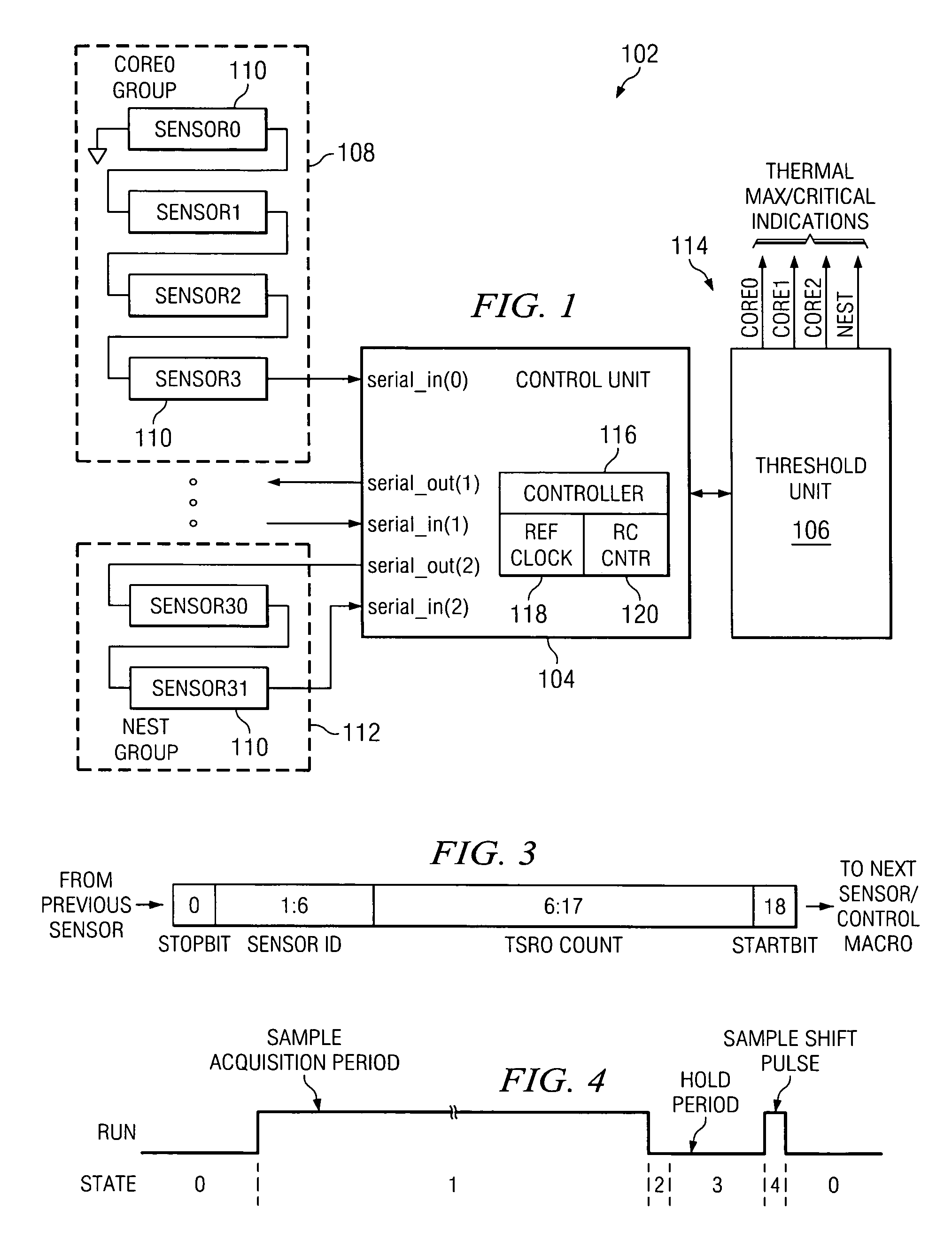
[0015]Referring to FIG. 1, there is shown a thermal monitor system 102 comprising an embodiment of the invention. System 102 is provided with a control unit 104 and a threshold unit 106, and is further provided with a number of sensor blocks or thermal sensors 110. FIG. 1 indicates that the embodiment shown thereby may include up to 32 sensors blocks 110, respectively referenced as sensor 0-sensor 31. In a useful arrangement, the sensor blocks are ordered in groups of four, such as group 108 and partial group 112.

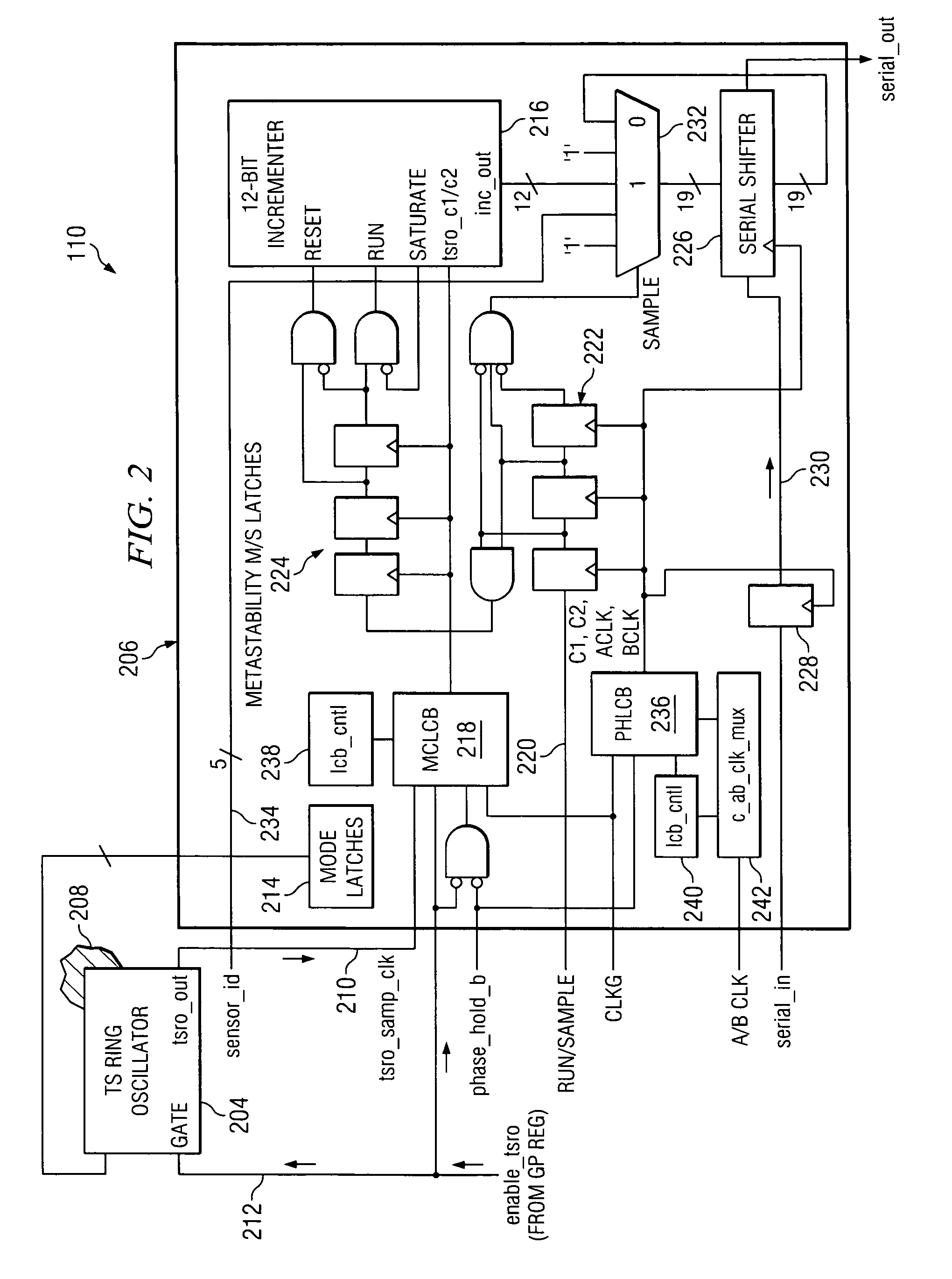
[0016]By providing multiple sensor blocks 110, the sensor blocks may be distributed throughout a chip or IC and placed at regions of high power density. As described hereinafter in further detail, each sensor includes a temperature-sensitive ring oscillator (TSRO) having an output frequency that varies inversely with its temperature. Each thermal sensor 110 is further provided with an incrementer, for counting successive pulses of the oscillator output signal, and with a sh...


PUM


Abstract

A system and method are provided for monitoring temperature within a specified integrated circuit. Usefully, the system comprises at least one oscillator device proximate to the integrated circuit for generating signal pulses at a frequency that varies as a function of the temperature adjacent to the oscillator device. The system further comprises a control unit for establishing sample acquisition periods of invariant time duration based on an time invariant reference clock. A sampling component is coupled to count the number of pulses generated by the oscillator device during each of a succession of the time invariant sample acquisition periods, and a threshold component responsive to the respective count values for the succession of sample acquisition periods provides notice when at least some of the count values have a value associated with a prespecified excessive temperature level.

Description

BACKGROUND OF THE INVENTION[0001]1. Technical Field[0002]The invention disclosed and claimed herein generally pertains to a system and method for monitoring thermal conditions in a processor chip or other integrated circuit (IC), in order to detect unacceptable temperature levels. More particularly, the invention pertains to a system of the above type wherein thermal sensors placed in a chip or IC each includes an oscillator for generating signal pulses at a frequency that varies as a function of the adjacent temperature. Even more particularly, the invention pertains to a system of the above type wherein the oscillator pulses are counted during sample acquisition periods of fixed or unvarying time duration.[0003]2. Description of Related Art[0004]Previously, thermal sensors for use in processors or other integrated circuits, such as IBM power processors, have used the functional clock of the processor to sample an asynchronous thermally sensitive device such as a ring oscillator (P...

Claims


Application Information

Patent Timeline
Patent Type & Authority Patents(United States)
IPC IPC(8): G06F17/40
CPCG01K7/32G01K7/425H01L23/34Y10S323/907H01L2924/0002H01L2924/00
Inventor FLOYD, MICHAEL STEPHENLAZARUS, ASHER SHLOMOMONWAI, BRIAN CHAN
Owner INT BUSINESS MASCH CORP
Why Eureka
Try Eureka