Valve control device reducing noise
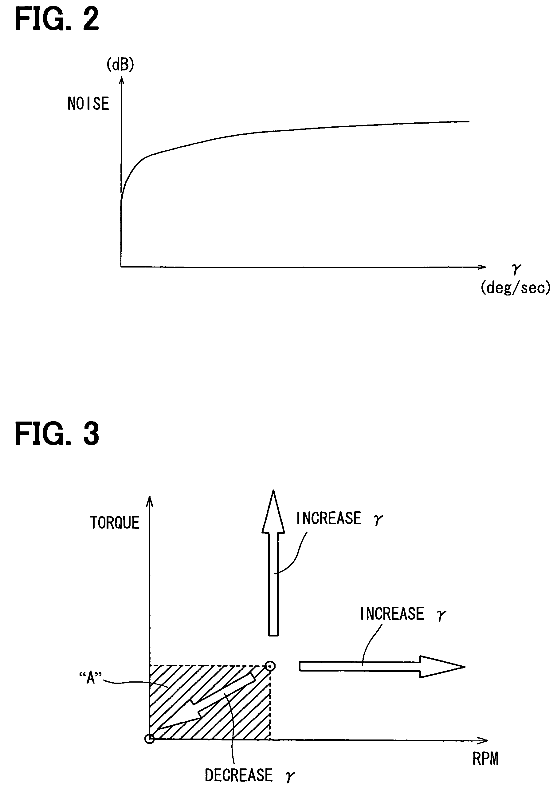
a control device and valve technology, applied in the direction of electric control, machines/engines, mechanical equipment, etc., can solve the problems of increasing annoyance for vehicle occupants, noise will be caused, etc., and achieve the effect of reducing noise, driving speed of valves, and reducing valve driving speed
- Summary
- Abstract
- Description
- Claims
- Application Information
AI Technical Summary
Benefits of technology
Problems solved by technology
Method used
Image
Examples
first embodiment
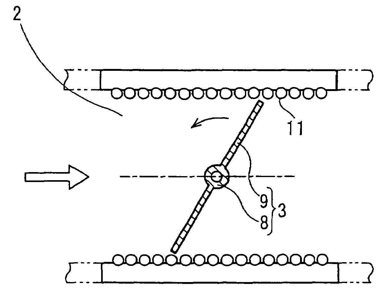
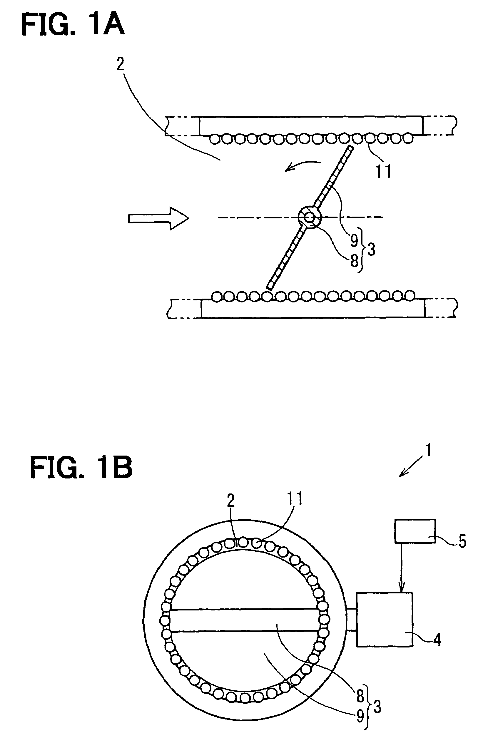
[0023]Referring to FIGS. 1A and 1B, a valve control device 1 according to the present invention is illustrated. The valve control device 1 drives and controls a valve 3 such as a throttle valve, an exhaust gas recirculation valve (EGR valve) or an exhaust gas restriction valve located in a fluid passage 2, through which a fluid taken or discharged by an engine passes.
[0024]The valve control device 1 is installed to the fluid passage 2 that performs air intake or gas exhaust with the engine. The valve control device 1 has the valve 3, an electric motor 4, and an electronic control unit (ECU) 5. The valve 3 regulates a flow rate of the intake air or exhaust gas. The electric motor 4 is an actuator that drives the valve 3. The ECU 5 operates as a controller that drives and controls the valve 3 by controlling the operation of the electric motor 4.
[0025]For example, the valve 3 is a butterfly valve having a shaft portion 8 connected to a rotary shaft (not shown) of the electric motor 4 a...
second embodiment
[0039]Referring to FIG. 5, a control mode of a valve control device 1 according to the present invention is illustrated. As shown in FIG. 5, the cleaning mode and the cleaning opening degree pattern are divided in two steps. The cleaning mode is divided into a first step in which the engine rotation speed RPM decreases to zero after the start of the engine stop and a second step in which the engine rotation speed RPM is zero. In this embodiment, the opening degree change rate and a driving range (opening degree amplitude) of the valve 3 during the elimination of the deposit 11 are selected from the driving patterns, and are corrected in accordance with the engine rotation speed.
[0040]The opening degree amplitude of the second step is set smaller than that of the first step. More specifically, the opening degree amplitude at the time when the engine rotation speed is zero is set smaller than the opening degree amplitude at the time when the engine rotation speed is greater than zero....
third embodiment
[0043]Referring to FIG. 6, a control mode performed by a valve control device 1 according to the present invention is illustrated. The valve control device 1 of this embodiment changes the valve opening degree change rate and the opening degree amplitude of the valve 3 in accordance with the engine rotation speed RPM when the elimination of the deposit 11 is performed. Even after the control mode is switched to the cleaning mode, the engine rotation speed RPM is monitored, and the opening degree change rate and the opening degree amplitude are corrected in accordance with the engine rotation speed RPM. Thus, in the cleaning opening degree pattern of this embodiment, both of the opening degree change rate and the opening degree amplitude are corrected to gradually decrease in accordance with the engine rotation speed RPM as shown in FIG. 6. As a result, the annoyance due to the noise accompanying the elimination of the deposit 11 can be further reduced when the engine rotation speed ...
PUM
 Abstract
Description
Claims
Application Information
 - R&D
- Intellectual Property
- Life Sciences
- Materials
- Tech Scout
- Unparalleled Data Quality
- Higher Quality Content
- 60% Fewer Hallucinations
Browse by: Latest US Patents, China's latest patents, Technical Efficacy Thesaurus, Application Domain, Technology Topic, Popular Technical Reports.
© 2025 PatSnap. All rights reserved.Legal|Privacy policy|Modern Slavery Act Transparency Statement|Sitemap|About US| Contact US: help@patsnap.com


