Biblock or multiblock transverse member and method for the production thereof

Inactive Publication Date: 2007-04-03
RAIL ONE
View PDF15 Cites 4 Cited by
  • Summary
  • Abstract
  • Description
  • Claims
  • Application Information

AI Technical Summary

Benefits of technology

[0003]It is therefore an object of the invention to configure a two-block or multi-block railroad tie of the type mentioned above, which can be produced easily and ensures a more advantageous, damage-free transport to the building site.
[0008]For this construction as bar joists, it can very easily be arranged that the protruding sections of the bar joists are sufficiently long, so that they mutually overlap in every case. By slightly bending up the one bar joist, it can readily overlap the protruding bar joist of the adjoining individual block, whereupon the mutually overlapping parts can be clamped, bolted or preferably welded.
[0009]Moreover, a connection, for which the protruding sections of the bar joists are constructed shortened, so that they are still at a distance from one another for the final assembly, is achieved particularly easily. The connection can then be brought about by a correspondingly somewhat larger bar joist piece, which is placed simply ever the mutually opposite bar joist ends of the individual blocks and then, as already indicated, clamped together with or bolted or welded to these.

Problems solved by technology

This method of producing the complete ties, and this applies, of course, particularly to multi-block railroad ties, such as those used, for example, at the switch points, has the disadvantage that the very long and, with that, also heavy railroad ties can be transported only awkwardly from the manufacturing plant to the far-removed building site.
In so doing, the danger also exists, in particular, that the long railroad ties will be damaged during this transport and, especially, will be bent, so that they are no longer aligned accurately for the desired gauge.

Method used


Image

  • Biblock or multiblock transverse member and method for the production thereof
  • Biblock or multiblock transverse member and method for the production thereof
  • Biblock or multiblock transverse member and method for the production thereof

Examples


Embodiment Construction

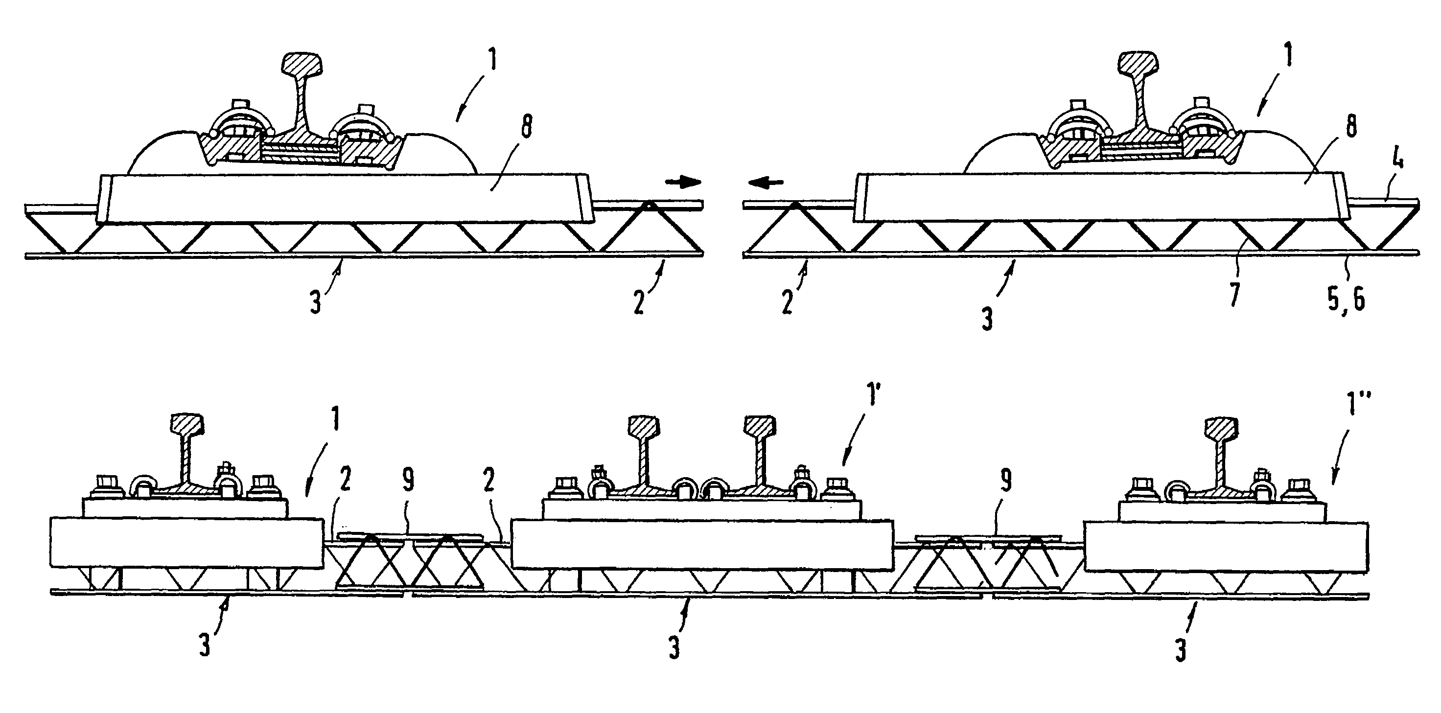
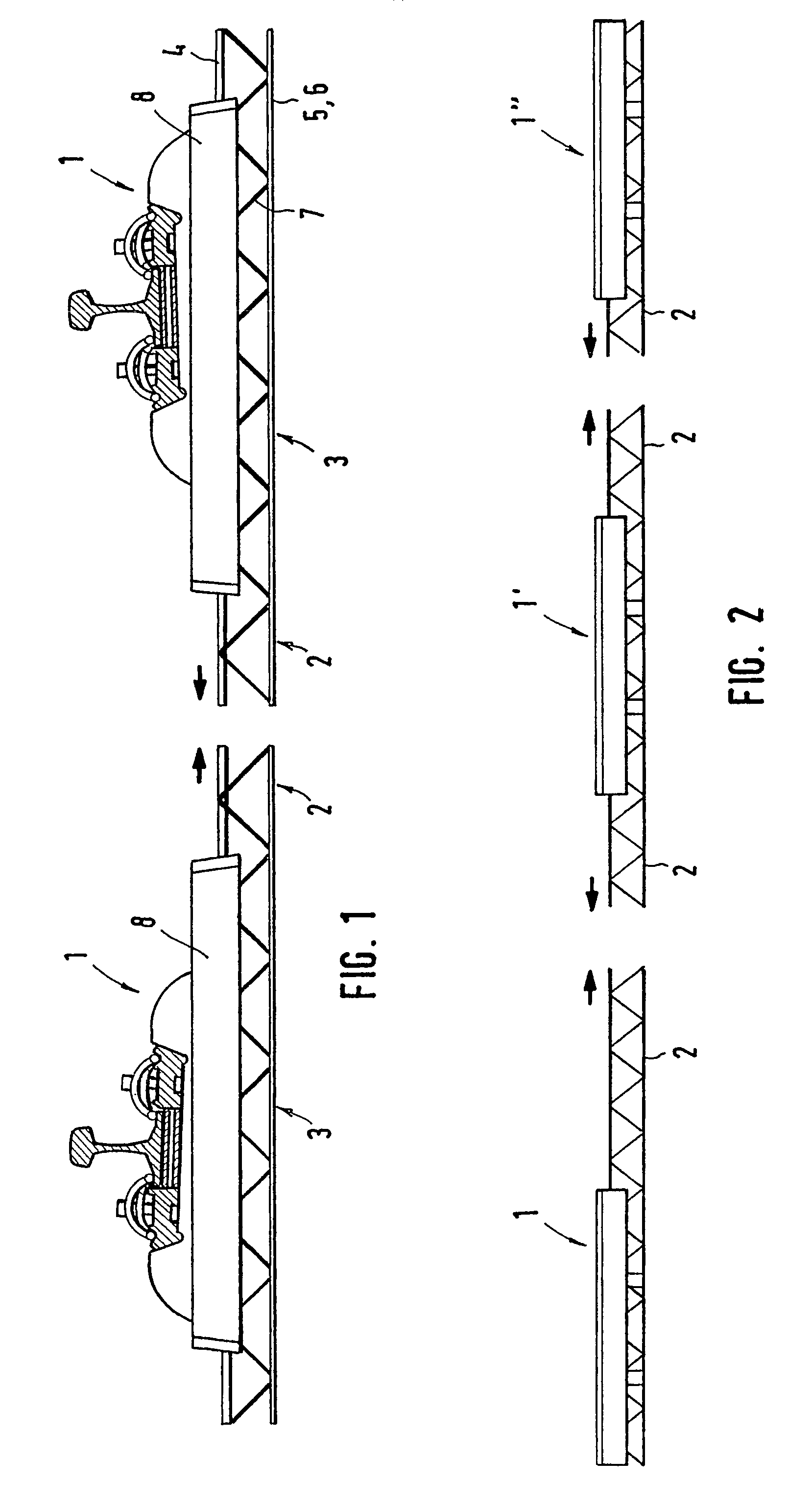
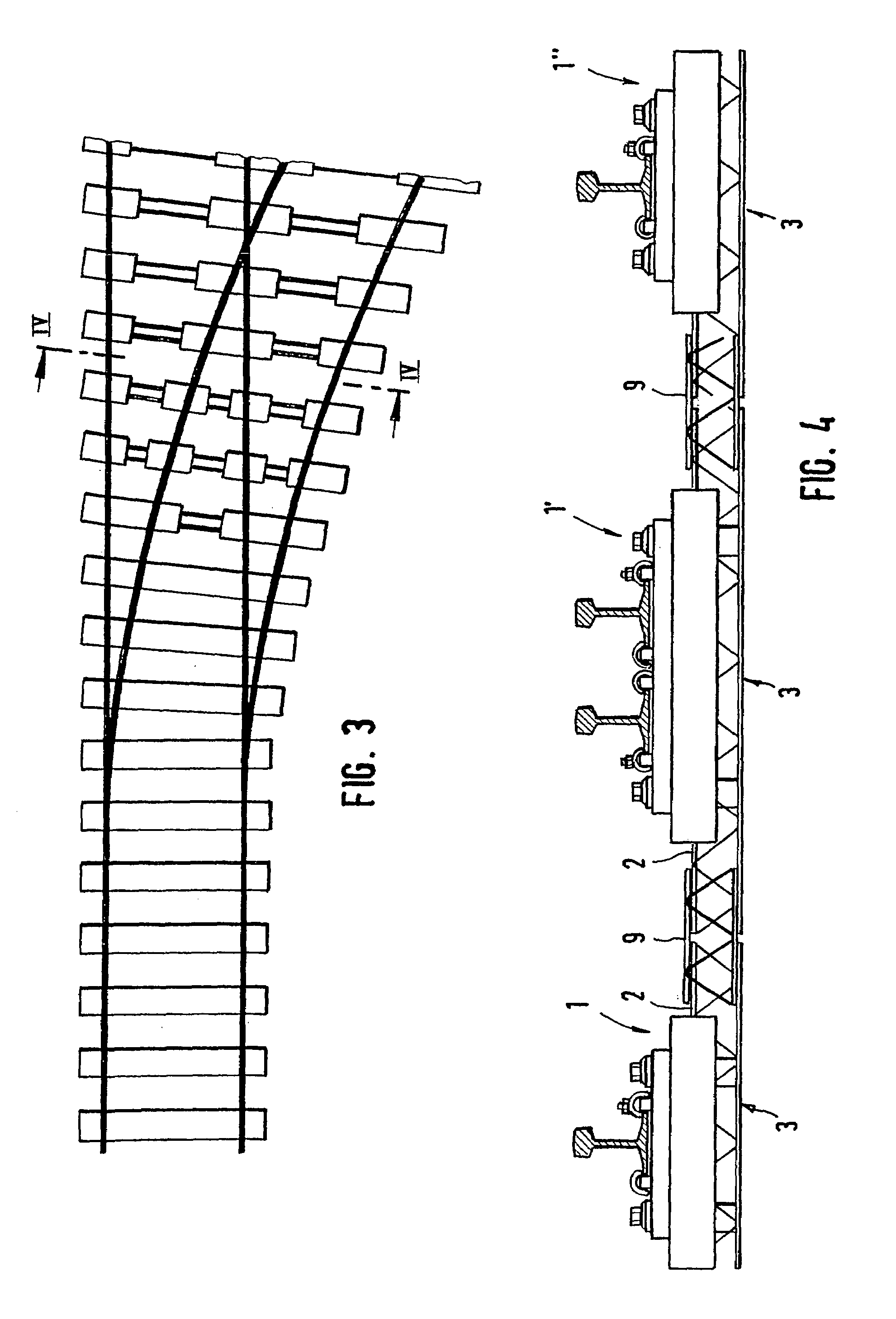
[0018]FIG. 1 shows a two-block railroad tie especially for a solid pavement, with individual blocks 1 of identical construction, which are to be connected with one another and which merely are rotated by 180°, so that the reinforcing parts 2 protruding from them, after an appropriate alignment of the individual blocks, can be connected with one another with the help of a gage. For this purpose, either appropriate connecting pieces can be placed down, which are connected with the two reinforcing parts 2, or the reinforcing parts are offset laterally, so that, when the individual blocks 1 are aligned axially, being laterally offset, they overlap one another and, in this way, can be welded together. For the embodiment of individual blocks 1 shown, the reinforcement of which is formed by one or optionally also several V-shaped, angled bar joists 3, for which in each case three reinforcing rods 4, 5 and 6, which extend parallel to one another, are connected with one another by zigzag-sha...


PUM


Abstract

A biblock or multiblock transverse member is provided with concrete blocks which includes plates connected to each other with the aid of an incorporated reinforcement elements. The transverse member consists of many individual prefabricated blocks whose two reinforcement elements are interconnected, more particularly welded.

Description

BACKGROUND OF THE INVENTION[0001]The invention relates to a two-block or multi-block railroad tie with concrete blocks, which carry the rail supports and are connected with one another by tied-in reinforcing parts, as well as to a method for producing such two-block or multi-block railroad ties.[0002]For previous methods of producing two-block railroad ties or also multi-block railroad ties, complete ties are produced in one mold and subsequently have to be equipped only with the rail-fastening means. This method of producing the complete ties, and this applies, of course, particularly to multi-block railroad ties, such as those used, for example, at the switch points, has the disadvantage that the very long and, with that, also heavy railroad ties can be transported only awkwardly from the manufacturing plant to the far-removed building site. In so doing, the danger also exists, in particular, that the long railroad ties will be damaged during this transport and, especially, will b...

Claims


Application Information

Patent Timeline
IPC IPC(8): E01B5/00E01B3/14E01B3/40E01B7/22
CPCE01B3/14E01B3/40E01B7/22E01B1/004
Inventor KOWALSKI, MARTIN
Owner RAIL ONE
Why Eureka
Try Eureka