
Shaped trilobal particles

Inactive Publication Date: 2007-04-03
SHELL OIL CO
View PDF9 Cites 14 Cited by
  • Summary
  • Abstract
  • Description
  • Claims
  • Application Information

AI Technical Summary

Benefits of technology

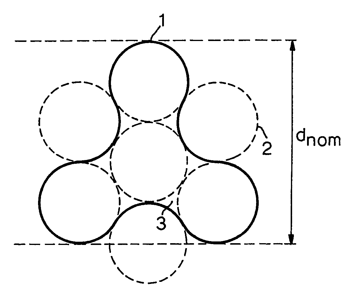
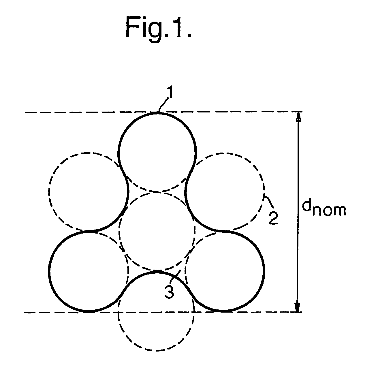
[0009]It has been found that the particles according to the present invention, having a larger surface-to-volume ratio than corresponding conventional “trilobal” particles of similar size, suffer substantially less from pressure drop than such corresponding conventional “trilobal” particles. Moreover, the shape of the particles according to the present invention allows a certain degree of “packing” which according to the teaching of EP-A-220993 would be detrimental with respect to pressure drop.

Problems solved by technology

Since many of the findings in the art are conflicting and pressure drop problems continue to be in existence, especially when surface-to-volume ratios are increased by reducing particle size, there is still considerable room to search for alternative shapes of (optionally catalytically active) particles which would diminish or even prevent such problems.

Method used


Image

  • Shaped trilobal particles
  • Shaped trilobal particles

Examples


example 2

[0039]Two experiments were carried out to compare flooding limits occurring when using conventional TL and particles having a shape according to the present invention (in this case, as shown in FIG. 1). The particles used in these experiments had the same shapes and compositions as those described in Example 1. A randomly packed bed of the TL particles showed a voidage of 40% and that of STL particles showed a voidage of 55%.

[0040]The experiments were carried out in a single column operated countercurrently with n-octane and nitrogen at ambient temperature and 2 bar absolute pressure. Care was taken to ensure uniform gas and liquid distribution. During the experiments, gas flow was increased at a constant liquid flow rate and pressure drop was measured across the column. The flood point is defined as the point where the pressure drop dependence on the gas velocity abruptly changes from an order between one and two to a substantial higher order.

[0041]In the experiment carried out wit...


PUM

PropertyMeasurementUnit
Lengthaaaaaaaaaa
Lengthaaaaaaaaaa
Diameteraaaaaaaaaa

Abstract

An elongate, shaped particle having three protrusions each extending from and attached to a central position aligned along the central longitudinal axis of the particle, the cross-section of the particle occupying the area encompassed by the outer edges of six outer circles around a central circle minus the area occupied by three alternating outer circles, wherein each of the six outer circles is touching two neighbouring outer circles and wherein three alternating outer circles are equidistant to the central circle, have the same diameter, and may be attached to the central circle.

Description

FIELD OF THE INVENTION[0001]The present invention relates to formed particles having a specific shape which particles may be employed in a wide variety of duties, catalytic or non-catalytic. They can be suitably applied to prevent or substantially reduce fouling of catalyst beds exposed to charges containing fouling material, thereby reducing increases in pressure drop. They can also be applied in hydroprocessing, e.g. in hydrodesulphurisation and hydrocracking, e.g. to produce middle distillates from paraffinic material obtained via a Fischer-Tropsch process.BACKGROUND OF THE INVENTION[0002]In the past a tremendous amount of work has been devoted to the development of particles, in particular catalytically active particles, for many different processes. There has also been a considerable effort to try to understand the advantages and sometimes disadvantages of effects of shape when deviating from conventional shapes such as pellets, rods, spheres and cylinders for use in catalytic ...

Claims


Application Information

Patent Timeline
IPC IPC(8): B32B5/16B01J35/02C10G45/04C10G47/02C10G47/12
CPCB01J35/026C10G45/04C10G47/02Y10T428/2982Y10T428/25Y10T428/2991B01J35/50B01J35/00
Inventor VAN HASSELT, BASTIAAN WILLEMMESTERS, CAROLUS MATTHIAS ANNA MARIA
Owner SHELL OIL CO
Learn More