Base station modulator/demodulator and send/receive method

Inactive Publication Date: 2007-04-03
JUMIPER NETWORKS INC
View PDF24 Cites 3 Cited by
  • Summary
  • Abstract
  • Description
  • Claims
  • Application Information

AI Technical Summary

Benefits of technology

[0026]According to the base station modulator / demodulator of the invention, for a base station wherein the usable band of the ATM cell between the base station and the higher rank station has been reduced due to a reduction in size / reduction in capacity of the base station, ATM cells of a plurality of base stations are logically multiplexed in a leased line between the base station and the higher rank station, the master base station terminates the ATM cell addressed thereto, and, at the same time, the send of ATM cell to a slave base station and the receive of ATM cell from the slave base station can be realized, whereby the waste of the leased line can be eliminated. Further, since the master base station and the slave base station have the same processing function, the thinking of “master / slave base station” is unnecessary and, thus, this facilitates system design. Furthermore, since the master base station has the same processing function as the slave base station, a further slave base station can be easily provided under the slave base station.

Problems solved by technology

The above-described conventional prior art techniques, however, had the following problems.
The first problem is such that when reduction in size / reduction in capacity of the base station has lead to a reduction in quantity of data for communication between the base station and the higher rank station and, consequently, the quantity of data has become smaller than the capacity of the leased line, in the mapping within the leased line, the proportion of the effective cell becomes larger than the proportion of the idol cell.
This creates wasteful line charge.
Since, however, there is no leased line suitable for the capacity, the system of the base station should be constructed in such a state that an unused band exists.

Method used


Image

  • Base station modulator/demodulator and send/receive method
  • Base station modulator/demodulator and send/receive method
  • Base station modulator/demodulator and send/receive method

Examples


Embodiment Construction

[0039]Preferred embodiments of the invention will be explained in detail in conjunction with the accompanying drawings.

[0040](1) Explanation of Construction

[0041]In data communication between a base station and a higher rank station in a mobile communication system, a transmission method is used wherein an existing leased line is used as a PM (physical media) sublayer and an ATM cell has been mapped in a leased line frame format.

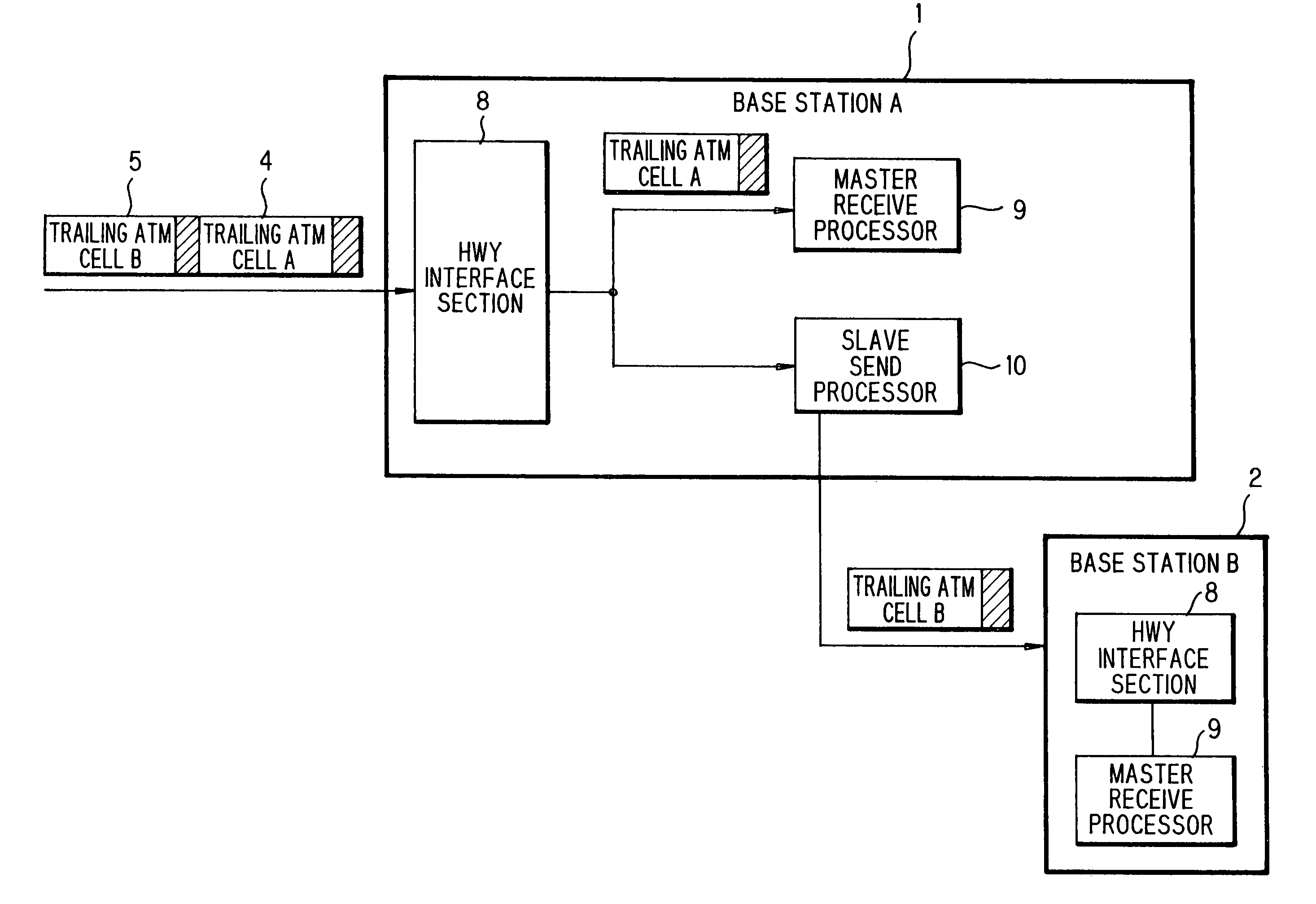
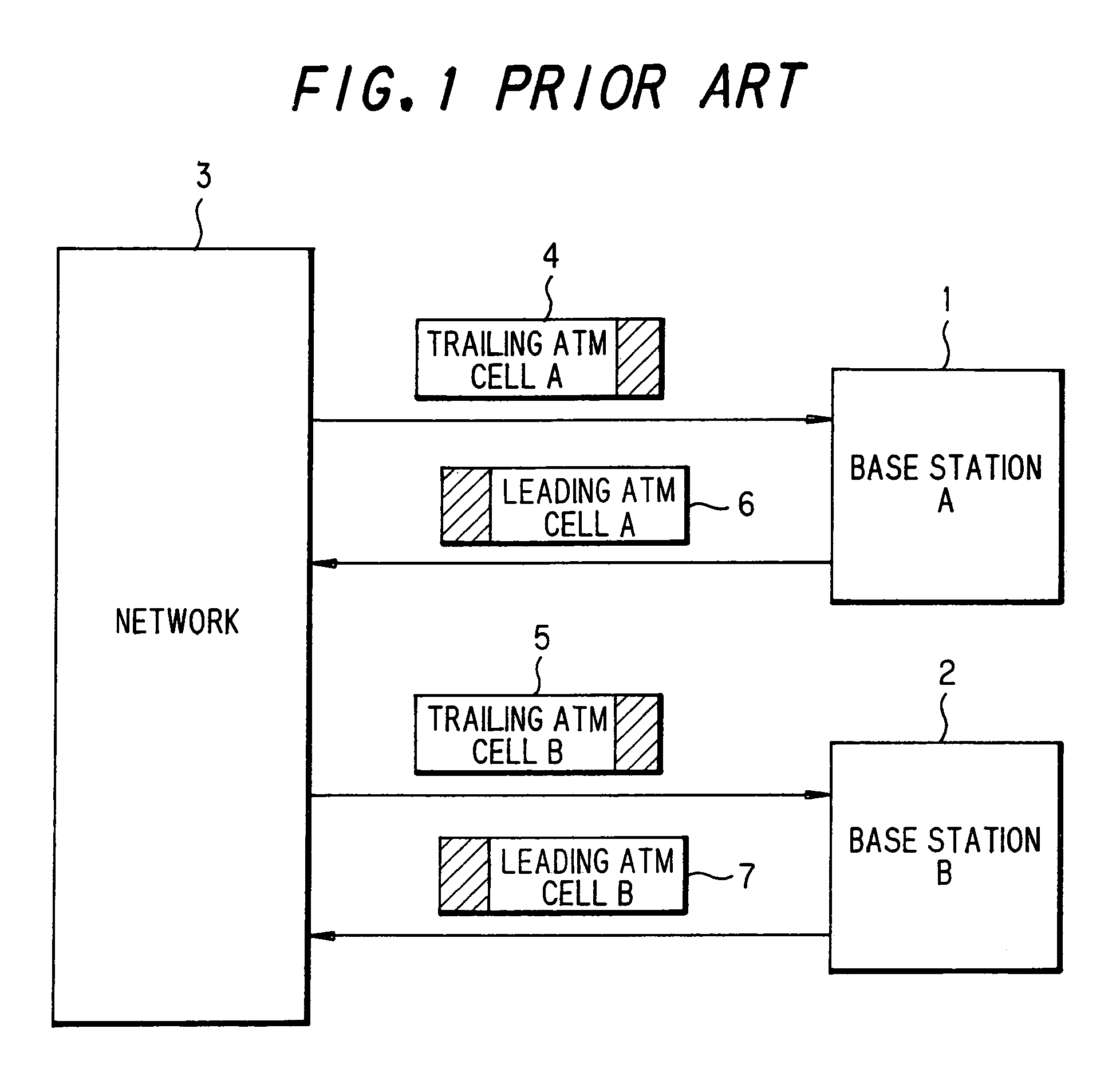
[0042]As shown in FIG. 5, the mobile communication system according to a preferred embodiment of the invention generally comprises a base station A1, a base station B2, and a network 3.

[0043]The above construction will be explained in detail. The base station A1 is connected to a higher rank station through a network 3. The network 3 and the base station A1 are connected to each other through a leased line. An ATM cell 25 (see FIG. 6) for the base station A1 and the base station B2 is multiplexed in the trailing data from the higher rank station. The trailin...


PUM


Abstract

A base station may include an interface section, a master receive processor, and a slave receive processor. An interface section may receive data from a higher rank station in the mobile communication system, the data may be received over a leased line. The master receive processor may receive the data from the higher rank station, determine whether the data from the higher rank station includes information destined for the base station, and terminate the data at the base station when the data from the higher rank station is determined to include information destined for the base station. The slave receive processor may receive the data from the higher rank station, determine whether the data from the higher rank station includes information destined for another base station, and transmit, over the leased line, the data to the another base station when the data from the higher rank station is determined to include information destined for the another base station.

Description

FIELD OF THE INVENTION[0001]The invention relates to a base station modulator / demodulator and an ATM (asynchronous transfer mode) cell send / receive method utilizing an ATM line, and more particularly to a base station modulator / demodulator and an ATM cell send / receive method suitable for the elimination of the waste of a leased line at the time of send / receive of ATM cells.BACKGROUND OF THE INVENTION[0002]There is a conventional mobile communication system which performs send / receive of ATM cells utilizing an ATM line between a higher rank station and a base station.[0003]FIG. 1 is a diagram showing an example of the construction of a conventional mobile communication system. In this mobile communication system, a base station A1 and a base station B2 are connected to a higher rank station through a network 3. The network 3 is connected to the base station through a leased line. Trailing data from the higher rank station is sent to the base station A1 through a leased line and to th...

Claims


Application Information

Patent Timeline
IPC IPC(8): H04Q7/24H04B7/26H04L47/43H04W4/00H04W56/00H04W88/08H04W92/12H04W92/20
CPCH04L12/5601H04W92/12H04L2012/5607H04L2012/5616H04L2012/5672H04W88/08H04W92/20
Inventor YAMAGIWA, HIROFUMI
Owner JUMIPER NETWORKS INC
Why Eureka
Try Eureka