Private VLANs

a virtual local area network and private technology, applied in the field of virtual local area networks, can solve the problems that the isolated or community port cannot receive traffic from the external lan connected, and achieve the effect of increasing the number of ports

Inactive Publication Date: 2007-04-03
CISCO SYSTEMS INC
View PDF7 Cites 32 Cited by
  • Summary
  • Abstract
  • Description
  • Claims
  • Application Information

AI Technical Summary

Benefits of technology

[0018]The VLANs defined in a first L2 switch chassis can be trunked to other L2 swi...

Problems solved by technology

However, an isolated or community port cannot receive traffic from the...

Method used


Image

  • Private VLANs
  • Private VLANs
  • Private VLANs

Examples


Embodiment Construction

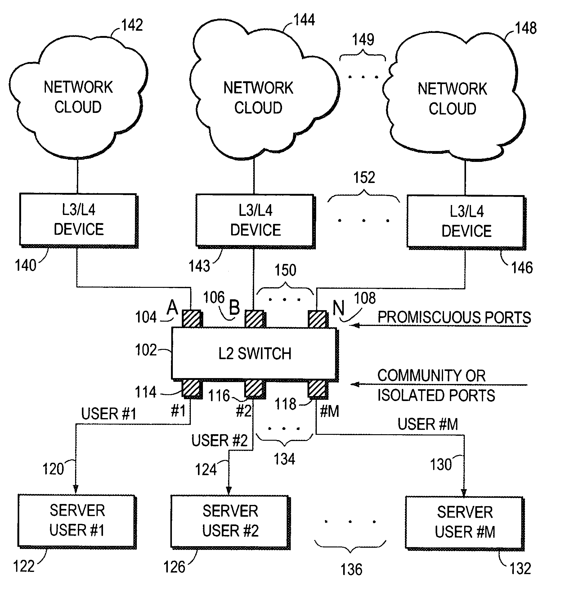
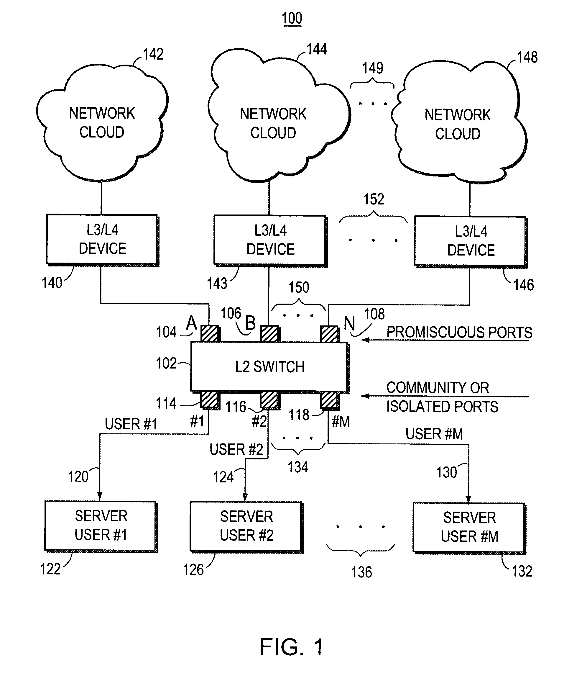
[0031]Turning now to FIG. 1, computer network 100 is shown.

[0032]L2 switch 102 has promiscuous ports, port A 104, port B 106, port N 108, etc. Promiscuous port 108 is indicated as “N”, indicating that an arbitrary number of promiscuous ports may be employed by L2 switch 102.

[0033]L2 switch 102 also has isolated or community ports, port #1114 is connected to user #1 VLAN 120, and user #1 VLAN 120 connects to user #1 server 122. Isolated or community port #2116 connects to user #2 VLAN 124, and user #2 VLAN 124 connects to user #2 server 126. Isolated or community port #M 118 is labeled “M” to indicate that L2 switch 102 may have an arbitrary number of isolated or community ports. Isolated or community port #M 118 connects to user #M VLAN 130, and user #M VLAN 130 connects to user #M server 132. “Three dots”134 indicate that L2 switch 102 may have a plurality of isolated or community ports, etc. “Three dots”136 indicate that a plurality of user servers, each connected to a different i...


PUM


Abstract

The invention uses a layer 2 switch (L2 switch), or bridge, to separate user's message traffic by use of Virtual Local Area Networks (VLANs) defined within the switch. Three new types of ports are defined, “promiscuous” ports “isolated” ports, and “community” ports. Three types of VLANs internal to the switch are defined, “primary” VLANs, “isolated” VLANs and “community” VLANs. The promiscuous ports are connected to layer 3 or layer 4 devices. Isolated ports and community ports are connected to individual user's servers, etc., and maintain traffic for each user separate from other users. The primary VLAN connects to all promiscuous ports, to all isolated ports, and to all community ports. The primary VLAN is a one way connection from promiscuous ports to isolated or community ports. An isolated VLAN connects to all promiscuous ports and to all isolated ports. The isolated VLAN is a one way connection from an isolated port to the promiscuous ports. A community VLAN is defined as connecting to a group of community ports, and also connecting to all of the promiscuous ports. The group of community ports is referred to as a “community” of community ports. A community VLAN is a one way connection from a community of ports to the promiscuous ports, but allows a packet received by one community port to be transmitted out of the switch, through the other community ports connected to that community VLAN.

Description

BACKGROUND OF THE INVENTION[0001]1. Field of the Invention[0002]The invention relates to Virtual Local Area Networks (VLANs), and more particularly to the use of VLANs to establish separation between different users of a shared switch.[0003]2. Background Information[0004]It is today a common computer network engineering practice to separate packet traffic belonging to different users by use of a router, a Layer 3 (L3) device. Separation of users' traffic is accomplished by assigning each user to a different subnetwork (subnet). A subnet is identified by a unique L3 address. The router then transmits a particular user's packets out through a port assigned to that subnet. However, only a limited number of bits in the L3 address (for example IP address) are assigned to the subnet, and so only a limited number of subnets may be addressed by a particular router. Subnet design is described by Andrew Tanenbaum in his book Computer Networks, Third Edition, published by Prentice Hall, Copyri...

Claims


Application Information

Patent Timeline
IPC IPC(8): H04L12/56
CPCH04L12/4641H04L12/467
Inventor EDSALL, THOMAS J.FOSCHIANO, MARCOFINE, MICHAELNOSELLA, THOMAS
Owner CISCO SYSTEMS INC
Why Eureka
Try Eureka