Sweep-type fingerprint sensor module

a fingerprint sensor and fingerprint sensor technology, applied in the field of fingerprint sensor modules, can solve the problems of optical fingerprint sensor drawback, inability to meet the requirement of real-time authentication, and inability to process fingerprint identification in real-time, so as to reduce the number of acquired fingerprint fragment images, reduce the cost, and simplify image processing

Active Publication Date: 2007-04-03
EGIS TECH
View PDF15 Cites 113 Cited by
  • Summary
  • Abstract
  • Description
  • Claims
  • Application Information

AI Technical Summary

Benefits of technology

[0017]By detecting the sweeping speed of the finger, the number of acquired fingerprint fragment imag

Problems solved by technology

However, the most serious drawback of the above-mentioned method is that the fingerprint identification cannot be processed in real-time, and thus cannot satisfy the requirement of real-time authentication, such as network authentication, e-business, portable electronics products, personal ID card, security system, and the like.
However, the optical fingerprint sensor has a drawback because it is large in size.
Furthermore, owing to the limitations in manufacturing the silicon integrated circuit, only 50 to 70 good dies may be formed in a 6″ wafer.
Thus, this expensive price may restrict the silicon fingerprint sensor in various consumer electronics applications such as notebook computers, mobile phones, personal digital assistants, computer peripheral product, or even personal ID cards embedded with the fingerprint sensor.
However, the method has to disadvantageously acquire many fingerprint fragment images and to re-construct them into a complete fingerprint

Method used


Image

  • Sweep-type fingerprint sensor module
  • Sweep-type fingerprint sensor module
  • Sweep-type fingerprint sensor module

Examples


Embodiment Construction

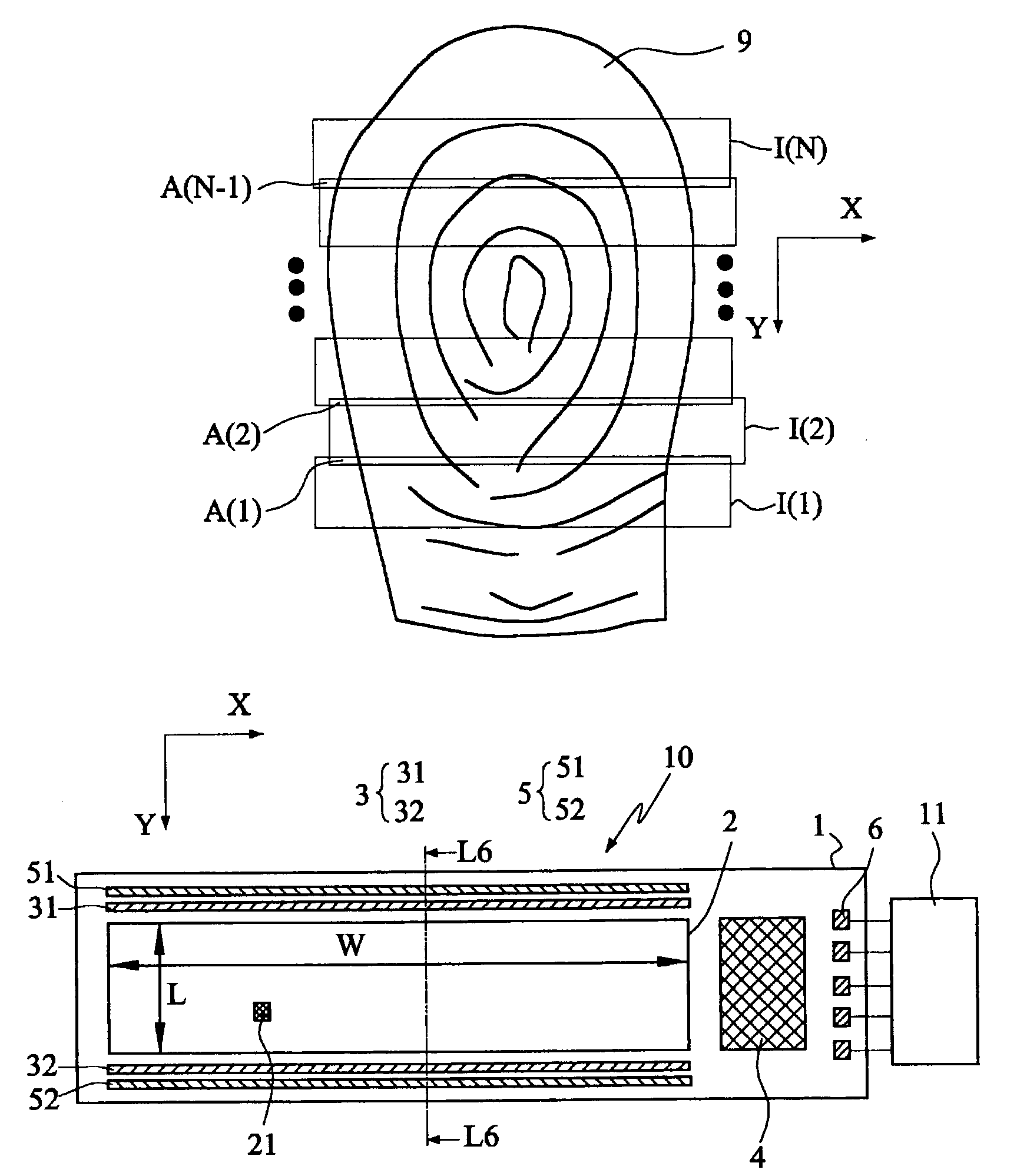
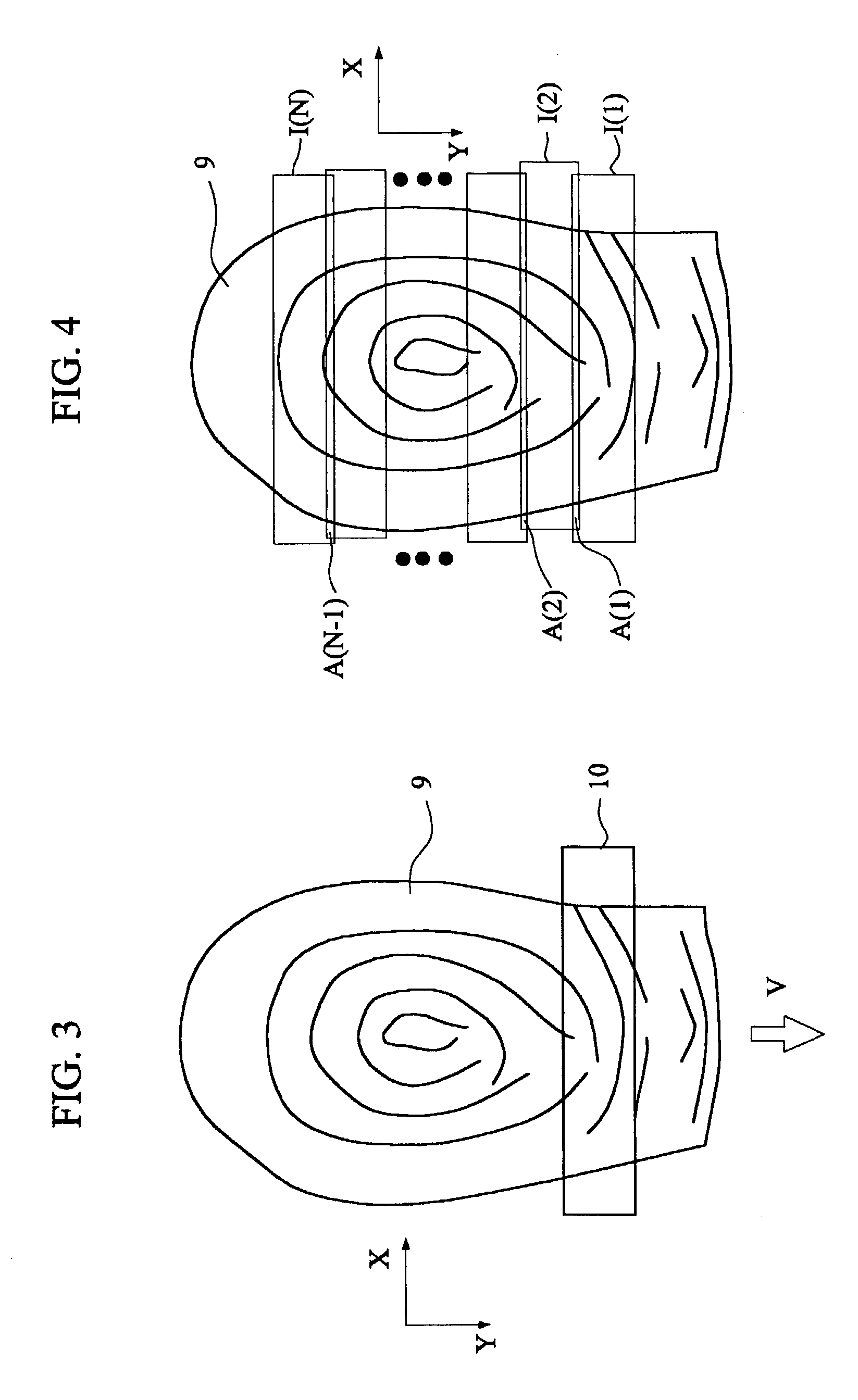
[0028]FIG. 3 is a schematic illustration showing a finger sweeping across a sweep-type fingerprint sensor of the invention, and FIG. 4 is a schematic illustration showing plural fingerprint fragment images acquired by the fingerprint sensor of FIG. 3. As shown in FIGS. 3 and 4, when a finger 9 sweeps across a sweep-type fingerprint sensor 10 at a speed V, the sweep-type fingerprint sensor 10 helps to detect the speed V of the finger 9, and acquires a plurality of fingerprint fragment images I(1) to I(N) according to the speed V, wherein N is a positive integral. The overlapped regions between adjacent two fingerprint fragment images are A(1) to A(N−1). The invention to be disclosed is suitable for minutia points extraction and matching, as will be discussed later.

[0029]The above-mentioned sensor may be embedded into any platform of any application device. When the finger 9 is placed on the platform and sweeps along the direction indicated by the arrow, the sensor 10 may sequentially...


PUM


Abstract

A sweep-type fingerprint sensor module includes a microprocessor and a sweep-type fingerprint sensor, which includes a substrate, and a sensing members array, a speed-detecting unit, and a processing circuit on the substrate. The array is composed of plural fingerprint sensing members. When the finger sweeps across the fingerprint sensor, the array sequentially acquires plural fingerprint fragment images from the finger with a sampling time interval. The speed-detecting unit is composed of first and second plate electrodes. The processing circuit processes and then outputs signals from the array and the speed-detecting unit. The microprocessor electrically connected to the processing circuit derives a sweeping speed of the finger by the time difference when the finger sweeps across the sensor surface and sequentially contacts the first and second plate electrodes, determines the sampling time interval and minimize the number of captured fragment images for re-construction of the initial complete fingerprint image.

Description

BACKGROUND OF THE INVENTION[0001]1. Field of the Invention[0002]The invention relates to a sweep-type fingerprint sensor module and a sensing method therefor, and more particular to a sweep-type fingerprint sensor module having a speed-detecting unit and a sensing method therefor.[0003]2. Description of the Related Art[0004]There are many known techniques of identifying an individual through the identification of the individual's fingerprint. The use of an ink pad and the direct transfer of ink by the thumb or finger from the ink pad to a recording card is the standard way of making this identification. Then, an optical scanner scans the recording card to get an image, which is then compared to fingerprint images in the computer database. However, the most serious drawback of the above-mentioned method is that the fingerprint identification cannot be processed in real-time, and thus cannot satisfy the requirement of real-time authentication, such as network authentication, e-busines...

Claims


Application Information

Patent Timeline
IPC IPC(8): G06K9/00
CPCG06K9/0002G06K9/00026G06V40/1335G06V40/1306
Inventor CHOU, BRUCE C. S.
Owner EGIS TECH
Why Eureka
Try Eureka