Safety razor with pivot point shift from center to guard-bar under applied load

a safety razor and pivot point technology, applied in the field of safety razors, can solve the problems of increasing the likelihood of nicks or cuts, and achieve the effect of maintaining a safe shave and increasing the load on the pivot type razor

Inactive Publication Date: 2007-04-10
EDGEWELL PERSONAL CARE BRANDS LLC
View PDF36 Cites 102 Cited by
  • Summary
  • Abstract
  • Description
  • Claims
  • Application Information

AI Technical Summary

Benefits of technology

[0025]It is a general object of the invention to be able to increase loading on a pivot type razor while maintaining a safe shave.

Problems solved by technology

Generally, as the force of shaving (loading) increases, the likelihood of experiencing a nick or a cut increases.
This has the effect, for center point pivot systems, of not taking maximum advantage of the skin stretching and protection features of the guard-bar which limit blade exposure and protect against nicks and cuts; while for guard-bar pivot systems, do not taking maximum advantage of the multiple blades available in light loading situations where receiving nicks and cuts are far less likely (the aforementioned “tradeoffs”).

Method used


Image

  • Safety razor with pivot point shift from center to guard-bar under applied load
  • Safety razor with pivot point shift from center to guard-bar under applied load
  • Safety razor with pivot point shift from center to guard-bar under applied load

Examples


first embodiment

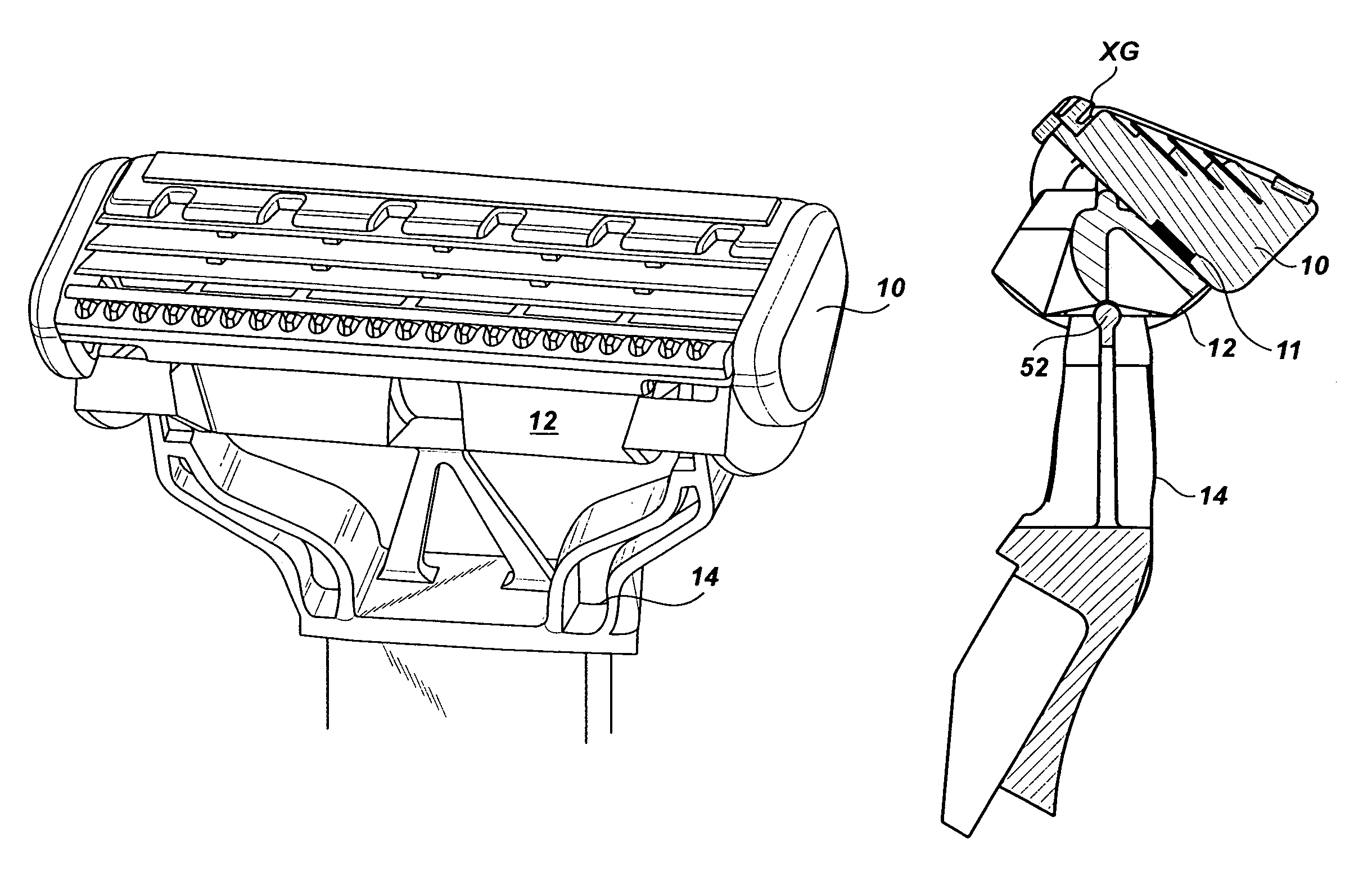
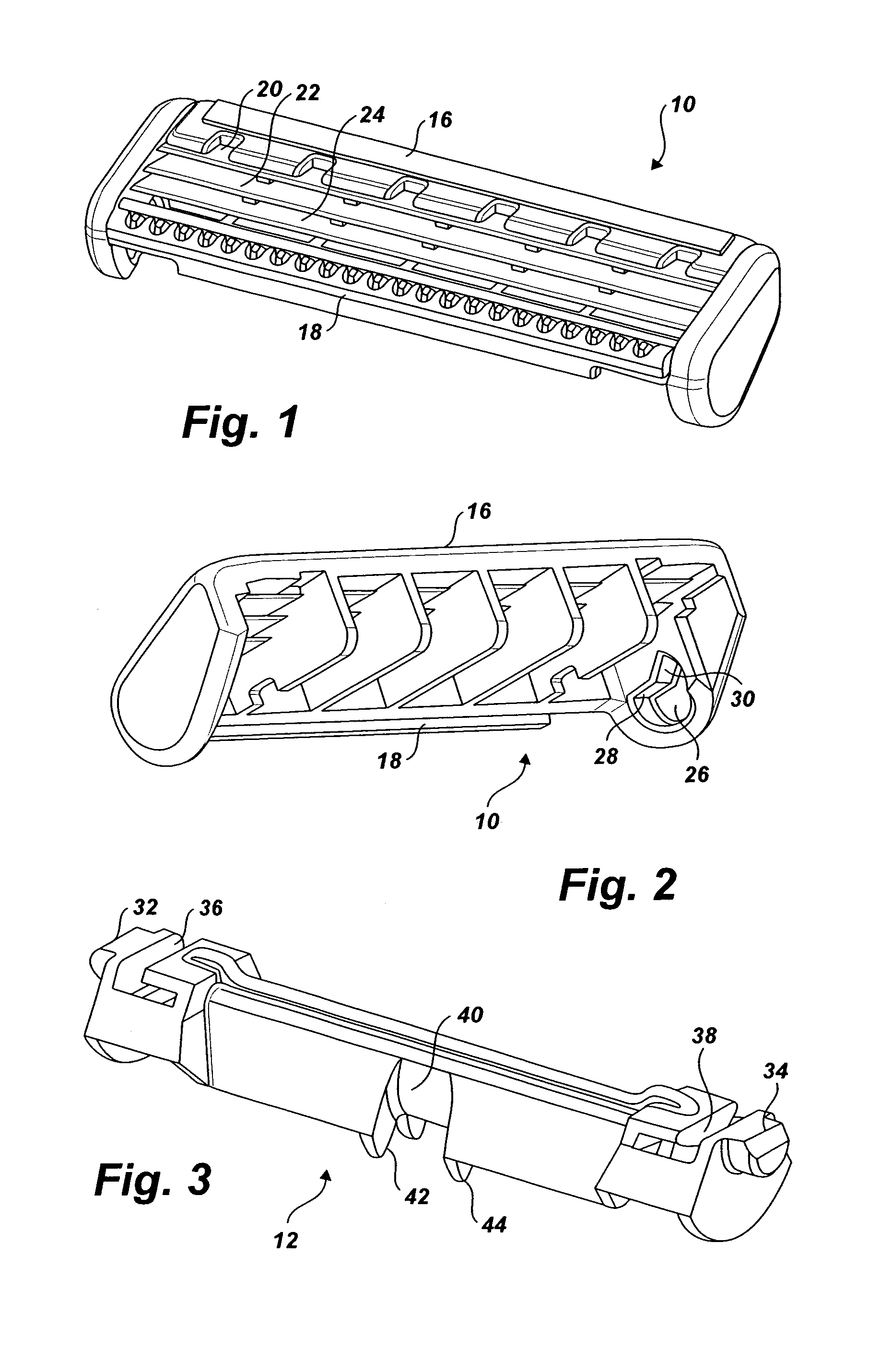
[0050]FIGS. 6–8 illustrate the first embodiment assembled. As seen best in FIG. 7, a biasing spring 11 is located between the blade assembly 10 and the pivot assembly 12. The spring 11 biases the blade assembly to the position shown in FIG. 7. As seen in FIG. 7, when the blade assembly is in this first position, application of loading to the blade assembly will cause the blade assembly 10 and the pivot assembly 12 to pivot about the center line “C” of the blade assembly. Upon the application of additional load sufficient to overcome the reactive force exerted by the spring 11, the blade assembly 10 will be moved against the spring 11 and will move to a second position relative to the pivot assembly 12. FIG. 8 illustrates the second position. When the blade assembly is in the second position, application of loading to the blade assembly will cause the blade assembly and the pivot assembly to pivot about the guard-bar axis “G”. From the foregoing, those skilled in the art will appreci...

second embodiment

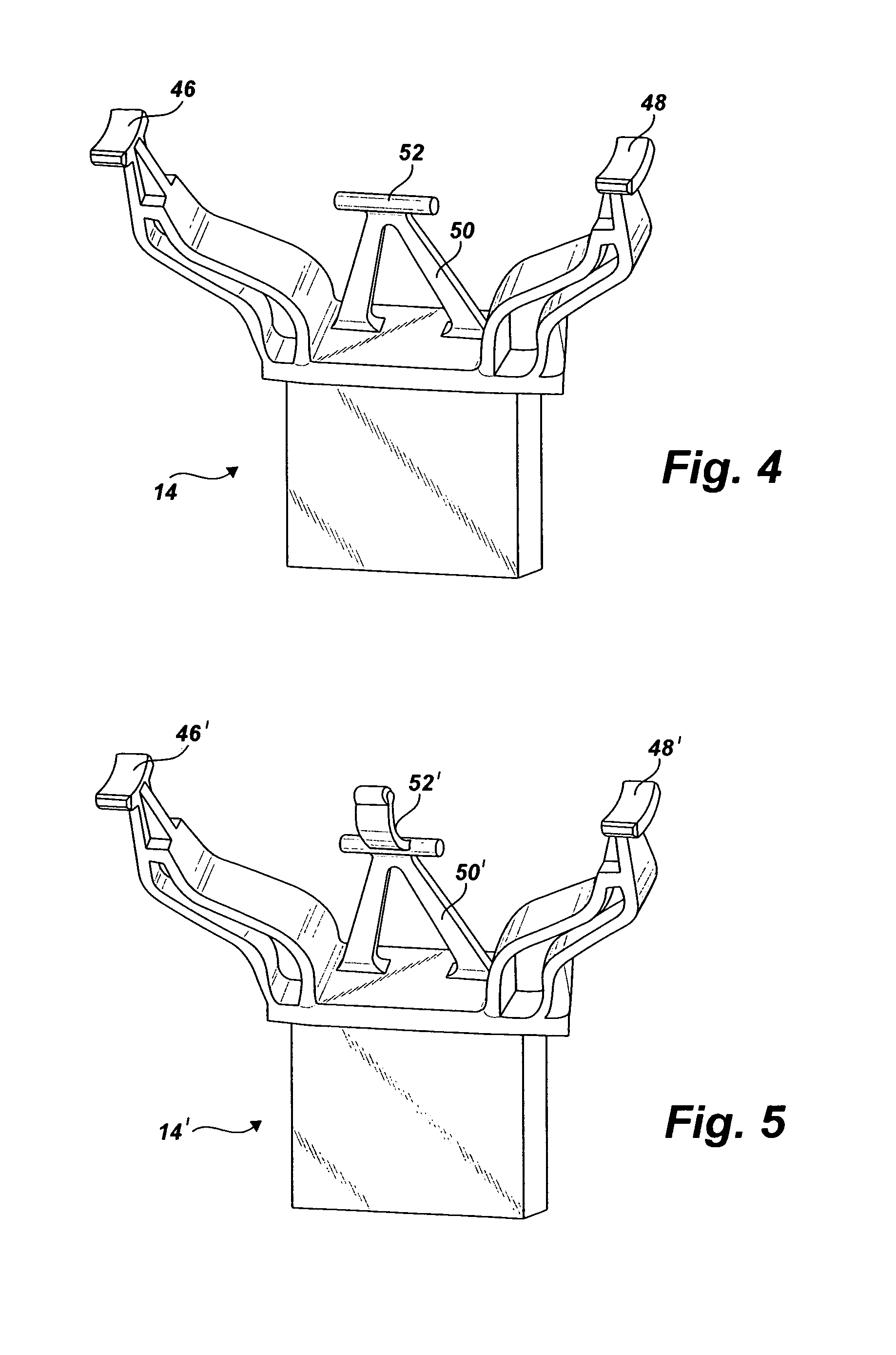
[0051]FIGS. 9–11 are similar to FIGS. 6–8 but illustrate the invention utilizing the pivot frame 14′. Those skilled in the art will appreciate that the pivot assembly 12 illustrated in FIGS. 9–11 is free to pivot relative to the pivot frame approximately 40° from the center position to the position shown in FIGS. 10 and 11. Further, it will be appreciated that the blade assembly is free to pivot relative to the pivot assembly approximately 45° from the position shown in FIG. 10 to the position shown in FIG. 11.

[0052]As described above, the invention increases safety by shifting the pivot point from a center point pivot (i.e., at the center blade on the shave plane), to a guard-bar pivot on the shave plane as shaving forces increase. The cartridge pivots relative to the pivot assembly shifting from a center pivot to a guard-bar pivot. It is returned to its initial position by the spring between the cartridge or blade assembly and the pivot assembly. The blade assembly and pivot assem...


PUM


Abstract

A safety razor which features a pivot point that shifts from a center point pivot substantially on the shave plane, to a guard-bar pivot substantially on the shave plane, as shaving forces increase to help prevent nicks and cuts, and provide a smooth shave.

Description

BACKGROUND OF THE INVENTION[0001]1. Field of the Invention[0002]The invention relates generally to safety razor shaving systems that include razor blade assemblies for mounting on handles via pivotal connections. More particularly, the invention relates to a safety razor which features a pivot point that shifts from a center point pivot (e.g., at the center blade of a triple blade razor, substantially on the shave plane), to a guard-bar pivot, substantially on the shave plane, as shaving forces increase to help prevent nicks and cuts, and provide a smooth shave.[0003]2. Brief Description of the Prior Art[0004]Safety razors are well known that employ blade units with a plurality of blades defining sharpened edges arranged to pass in succession over a skin surface being shaved.[0005]The invention is applicable to safety razors having blade units in the form of cartridges detachably mounted on a handle for replacement when the blade edges have become dulled; and to disposable safety ra...

Claims


Application Information

Patent Timeline
Patent Type & Authority Patents(United States)
IPC IPC(8): B26B21/00B26B21/14B26B21/22B26B21/52
CPCB26B21/225
Inventor RICHARD, PAUL
Owner EDGEWELL PERSONAL CARE BRANDS LLC
Why Eureka
Try Eureka