
Fuel injection system for an internal combustion engine

a fuel injection system and internal combustion engine technology, applied in the direction of filtration separation, lubricant mounting/connection, separation process, etc., can solve the problems of reducing the efficiency of the fuel system, and reducing so as to reduce the risk of fuel spillage during filter exchange and the complexity of the system

Inactive Publication Date: 2007-04-10
VOLVO TRUCK CORP
View PDF16 Cites 5 Cited by
  • Summary
  • Abstract
  • Description
  • Claims
  • Application Information

AI Technical Summary

Benefits of technology

[0005]One object of the invention is therefore to provide a fuel system that makes possible automated removal of air after filter exchange without the system being made more complicated or expensive.
[0006]The fuel system designed for this purpose comprises (includes, but is not necessarily limited to) a fuel tank, a fuel pump and a fuel filter located in a flow duct between the fuel pump and the fuel consumers of the engine. The flow duct comprises a valve chamber, located downstream of the fuel filter, with a valve cone arranged movably in the chamber between an upper valve seat and a lower valve seat. Further, an upper part of the valve chamber has an outlet for bleed to the fuel tank and the valve cone is provided with an inner passage with a valve seat which, under normal fuel pressure, interacts with a bleed cone that is movable in the passage. On the one hand, this design of the fuel system ensures that fuel spillage during filter exchange is minimized, and, on the other hand, that subsequent bleeding of the fuel system can take place automatically.

Problems solved by technology

This involves expensive workshop time and also a risk of fuel spillage because the abovementioned nipples are generally not closed before the fuel flows.
This device, however, can only facilitate the procedure for bleeding air from the fuel system, and further actions are required in order to remove air from the high-pressure side of the system.
Inclusion of this type of device therefore requires that the number of components in the fuel system be increased without fully solving the problem of facilitating the bleed procedure.

Method used


Image

  • Fuel injection system for an internal combustion engine
  • Fuel injection system for an internal combustion engine
  • Fuel injection system for an internal combustion engine

Examples


Embodiment Construction

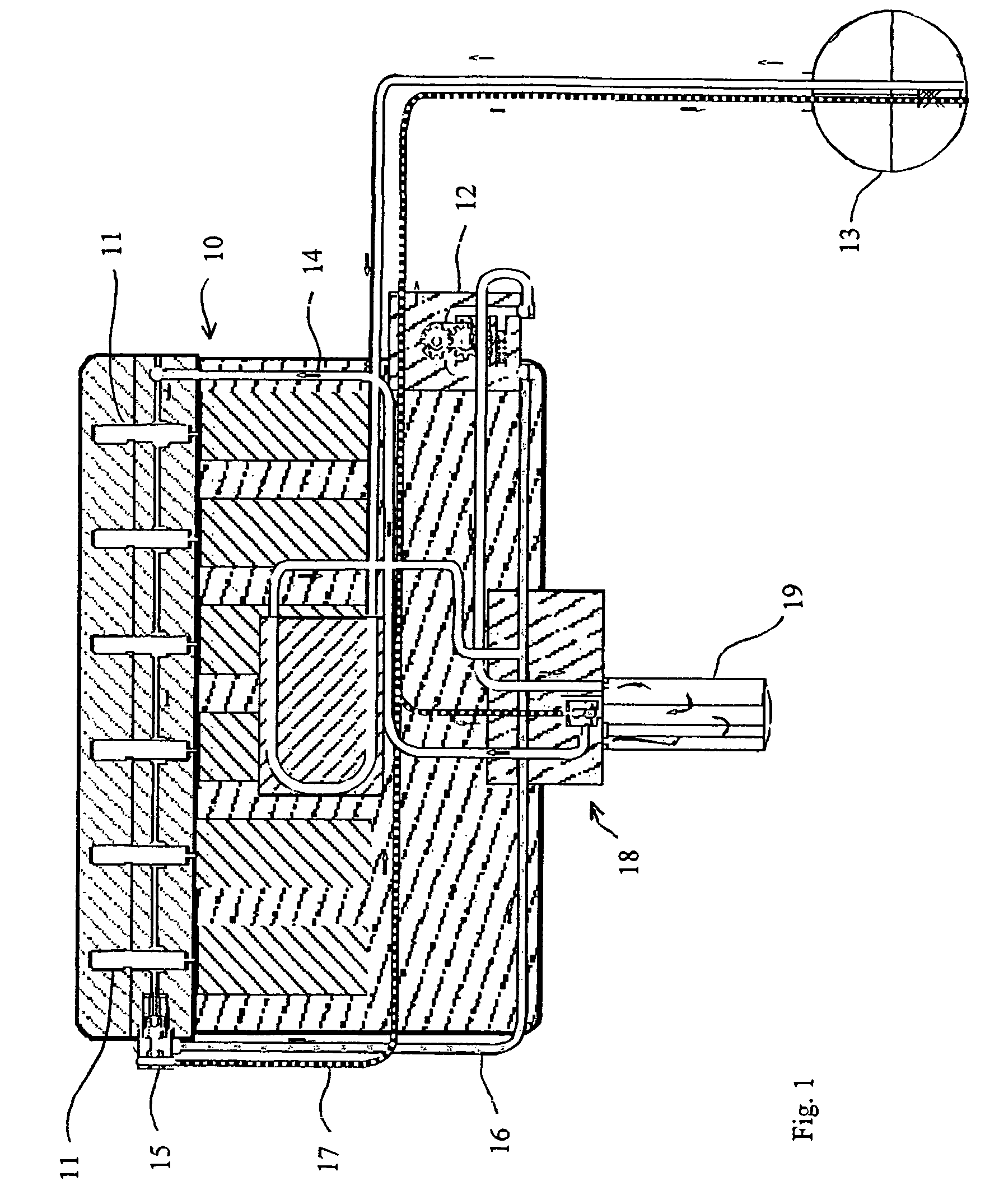
[0011]An internal combustion engine 10 is shown diagrammatically in FIG. 1 as a six-cylinder diesel engine with a corresponding number of injectors 11 of standard type. This engine can be used, for example, to drive a heavy truck.

[0012]Diesel fuel is fed by a pump 12 driven by the engine from a tank 13 via a common feeder line 14 to the injectors 11. A combination valve 15 for pressure control and bleeding is mounted downstream of the injectors 11. A return line 16 for uncombusted fuel is connected to the combination valve. A bleed line 17 is also connected to the combination valve, which bleed line communicates with the fuel tank 13.

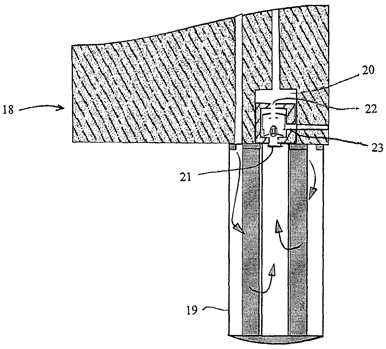
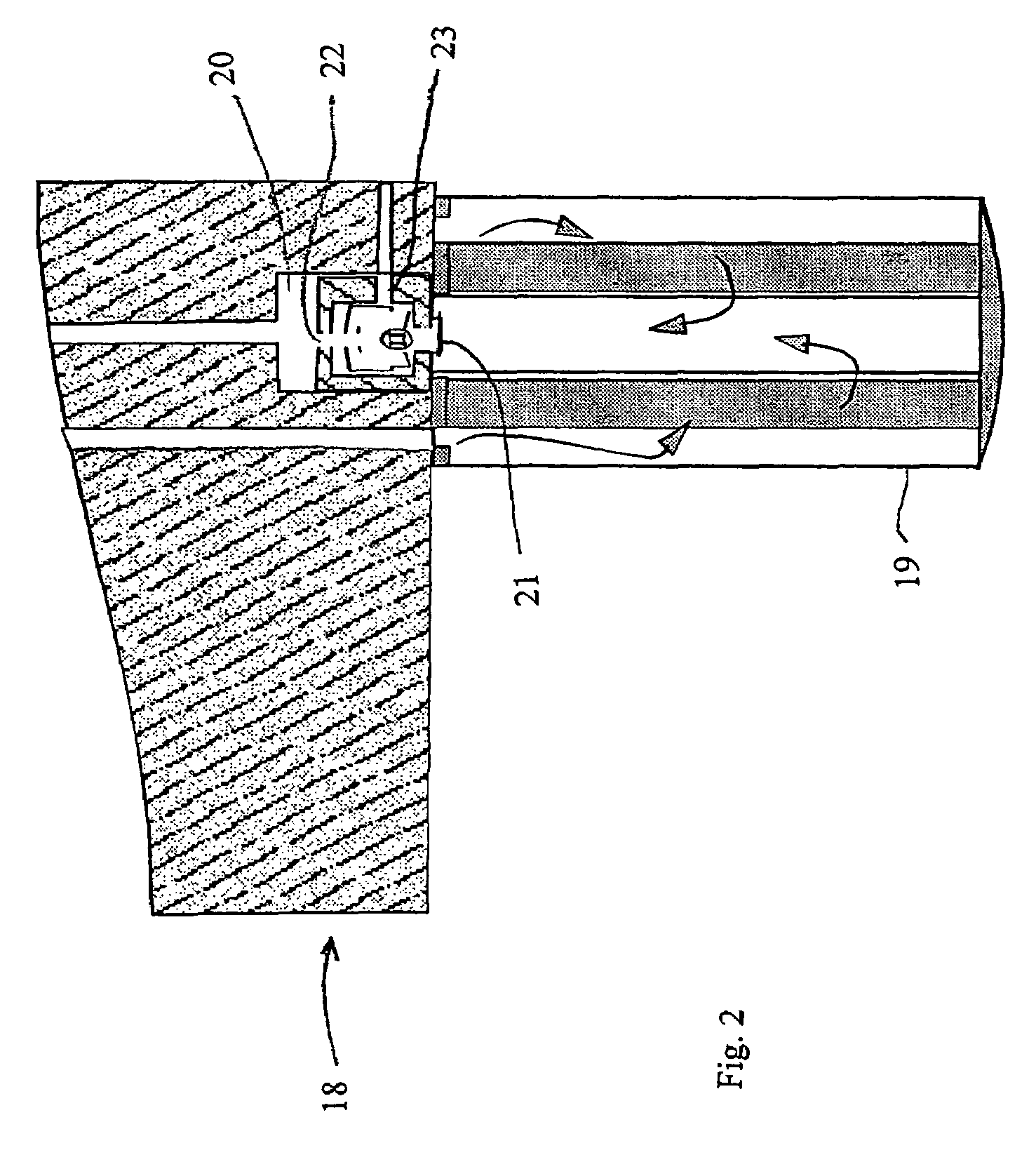
[0013]The fuel system also comprises a filter holder 18 with a fuel filter 19. The filter holder is shown in greater detail in FIG. 2 and is provided with a cylindrical valve chamber 20 that is located downstream of the fuel filter and is shown in greater detail in FIGS. 3–5.

[0014]The lower end wall 20a of the chamber is provided with a central inlet 21...


PUM

PropertyMeasurementUnit
pressureaaaaaaaaaa
weightaaaaaaaaaa
timeaaaaaaaaaa

Abstract

Method and arrangement for providing a fuel system for an internal combustion engine (10) that includes a fuel tank (13), a fuel pump (12) and a fuel filter (19) located in a flow duct (14) between the fuel pump and the fuel consumers (11) of the engine. The flow duct (14) includes a valve chamber (20), located downstream of the fuel filter, and having a valve cone (24) movably arranged in the chamber between an upper valve seat (20b) and a lower valve seat (27). The upper part of the valve chamber (20) has an outlet (22) for bleeding to the fuel tank (13). The valve cone (24) is provided with an inner passage (25) with a valve seat (25a) which, under normal fuel pressure, interacts with a bleed cone (26) that is movable in the passage (25).

Description

CROSS-REFERENCE TO RELATED APPLICATIONS[0001]The present application is a continuation patent application of International Application No. PCT / SE03 / 00884 filed 28 May 2003 which was published in English pursuant to Article 21(2) of the Patent Cooperation Treaty, and which claims priority to 1) Swedish Application No. 0201906-6 filed 19 Jun. 2002; and 2) U.S. Provisional Application No. 60 / 389,737 filed 19 Jun. 2002. Said applications are expressly incorporated herein by reference in their entireties.TECHNICAL FIELD[0002]The present invention relates to a fuel system for an internal combustion engine and that includes a fuel tank, a fuel pump and a fuel filter located in a flow duct between the fuel pump and the fuel consumers of the engine. The flow duct includes a valve chamber located downstream of the fuel filter and a valve cone arranged movably in the chamber between an upper valve seat and a lower valve seat.BACKGROUND[0003]Fuel systems for internal combustion engines are usua...

Claims


Application Information

Patent Timeline
Patent Type & Authority Patents(United States)
IPC IPC(8): F02M37/04B01D36/00F02M37/20F02M37/22F02M55/00F02M55/02F02M63/02
CPCB01D36/001F02M37/20F02M37/22F02M55/007F02M55/02F02M37/0023F02M63/0225F02M37/54
Inventor LARSSON, ANDERS
Owner VOLVO TRUCK CORP
Learn More