
Module for storing/drawing electricity in/from an electric accumulator applicable to photovoltaic systems, a photovoltaic system and a method of upgrading a photovoltaic system

a photovoltaic system and electric accumulator technology, applied in the field of photovoltaic systems, can solve the problems of inability to have photovoltaic systems which store, inability to combine two forms of use, and inability to obtain photovoltaic systems. the effect of simple and cost-effectiv

Active Publication Date: 2018-12-25
OTTOLINI DARIO
View PDF5 Cites 0 Cited by
  • Summary
  • Abstract
  • Description
  • Claims
  • Application Information

AI Technical Summary

Benefits of technology

The present invention aims to overcome the drawbacks of previous photovoltaic systems. The invention provides a simple and cost-effective solution to make the user core more independent from the public electric grid. The invention includes a module that has a two-way DC / DC converter that converts energy generated by the photovoltaic panel to store it in the accumulator and to supply it to the inverter. The module also includes power detector means to detect power flow between the user arrangement and the public electric grid, and the control unit controls the two-way DC / DC converter based on the signals generated by the power detector means. This allows for a more selective use of energy generated by the photovoltaic panel, reducing the amount of energy exchanged between the user arrangement and the public electric grid.

Problems solved by technology

The applicant realized that the above-described techniques do not allow to obtain a photovoltaic system which ensures a good degree of independence from the public electric grid to the user core for which it is installed.
Furthermore, it is not possible to have photovoltaic systems which store electricity which can be exploited in parallel to the public electric grid.
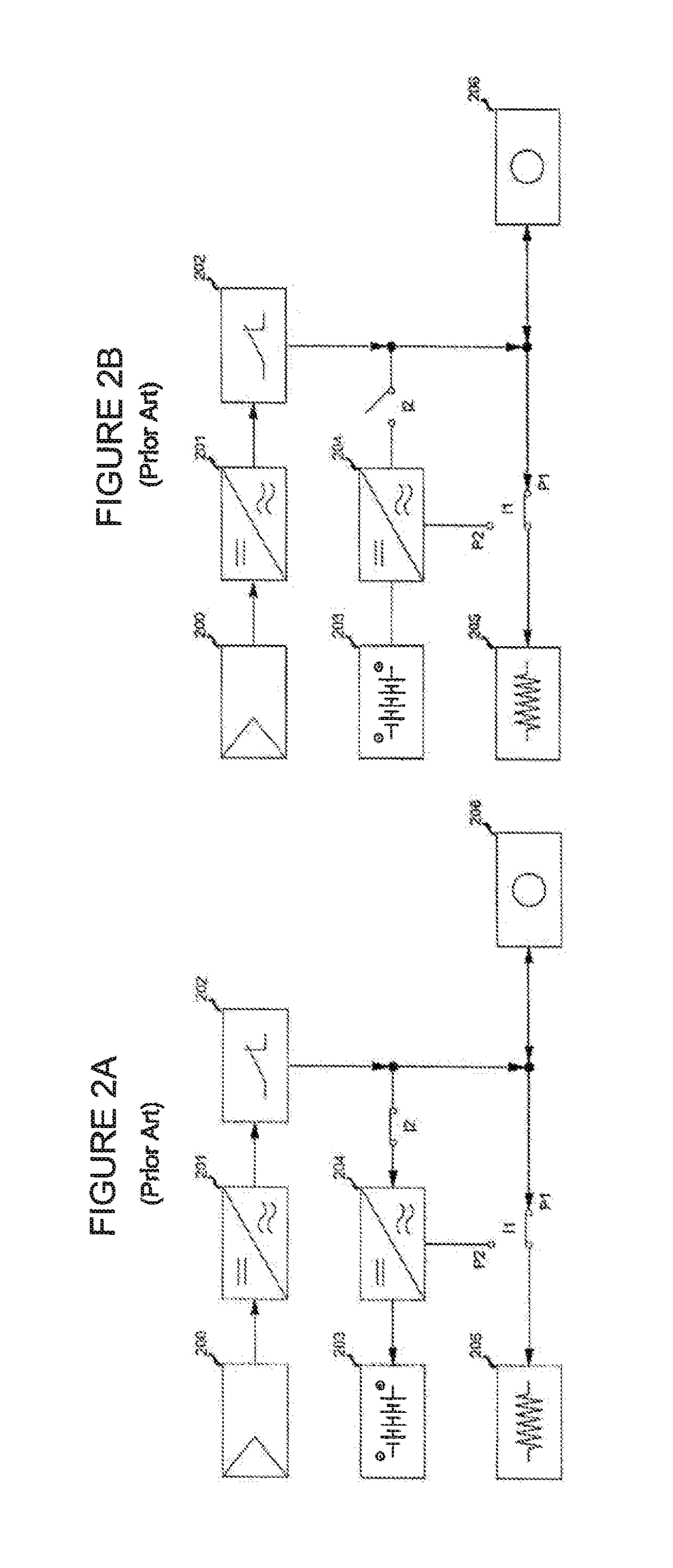
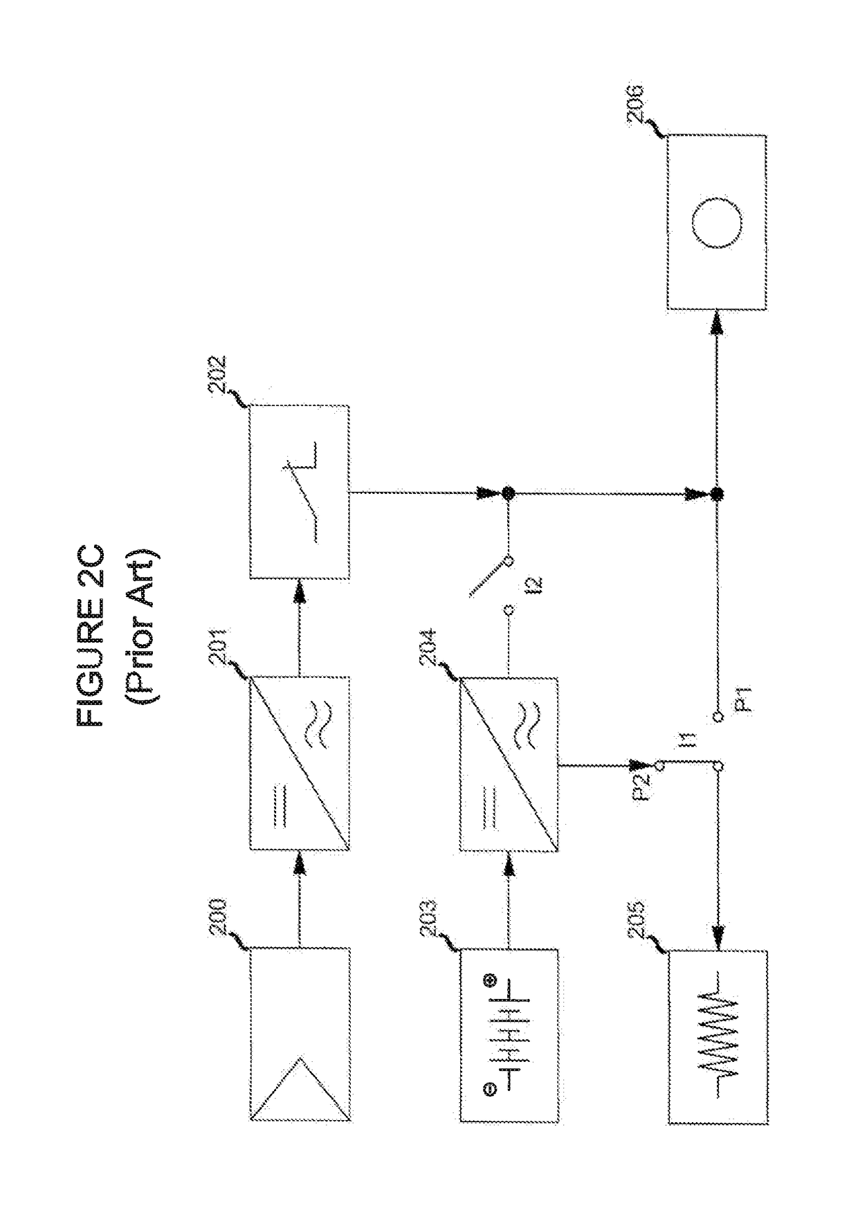
As mentioned, the most evolved systems allow to store the generated energy in an effective manner to use it when it is most required; however, in the current art, a user may draw energy either from the electric grid or from the accumulator, but these two forms of usage cannot be combined.
Furthermore, the installation of this type of systems is rather complex, the control logic and the switches which are set to provide the two operating conditions must be technologically advanced to ensure a constant supply of electricity also in moments of peak absorption to the user 205.
Each conversion step introduces a specific loss due to the conversion efficiency margin, thus the overall losses (i.e. the sum of the losses of each step) may be even considerable.
The general efficiency of these solutions is thus rather low.

Method used


Image

  • Module for storing/drawing electricity in/from an electric accumulator applicable to photovoltaic systems, a photovoltaic system and a method of upgrading a photovoltaic system
  • Module for storing/drawing electricity in/from an electric accumulator applicable to photovoltaic systems, a photovoltaic system and a method of upgrading a photovoltaic system
  • Module for storing/drawing electricity in/from an electric accumulator applicable to photovoltaic systems, a photovoltaic system and a method of upgrading a photovoltaic system

Examples


Embodiment Construction

[0040]The following description and the corresponding drawings are provided only by way of illustrative, non-limiting example of the present invention which can be implemented according to other, different embodiments.

[0041]The object of the present invention is conceived to be applied to photovoltaic systems, e.g. installed to supply electricity to residential type users, but not only, thus to new and existing systems.

[0042]FIG. 4 shows a first embodiment of a photovoltaic system to which a module for storing and drawing electricity in and from an accumulator 402 is applied. The verbs “store” and “draw” indicate the functions of the module according to the present invention: to store the energy generated by the photovoltaic system, in particular by the photovoltaic panel 401 in the accumulator 402, and to draw energy from the accumulator 402 to supply it to the inverter 404. To this end, the module comprises first terminals adapted to be connected to the photovoltaic panel 401 and ...


PUM


Abstract

The module according to the present invention is used for accumulating / drawing electricity in / from an electric accumulator (502); the module comprises first terminals and second terminals; the first terminals are adapted to be connected to a photovoltaic panel (501) and to an inverter (504), and the second terminals are adapted to be connected to the electric accumulator (502); the module comprises a conversion unit (503) adapted to be connected between the first terminals and the second terminals; the conversion unit (503) comprises, in turn, a two-way DC / DC converter (550) adapted to convert a first energy flow generated by the photovoltaic panel (401, 501) to store it in the accumulator (502) and a second energy flow drawn from the accumulator (502) to supply it to the inverter (504), the two-way DC / DC converter (450, 550) is configured to convert said first energy flow and said second energy flow in a selective manner. The module is characterized in that comprises: power detector means (507) adapted to be connected between a user arrangement (520), which comprises the inverter (504), in particular of the type with MPPT, and a user (506), and a public electric grid (508), and adapted to detect the power flowing between the user arrangement (520) and the public electric grid (508) and vice versa between the public electric grid (508) and the user arrangement (520); the conversion unit (403, 503) comprises a control unit (501) connected to the power detector means (507) and adapted to control the two-way DC / DC converter (550) as a function of signals generated by the power detector means (507). By means of such a module, it is possible to upgrade a photovoltaic system so as to minimize the electricity exchanges between the photovoltaic system and the public electric grid.

Description

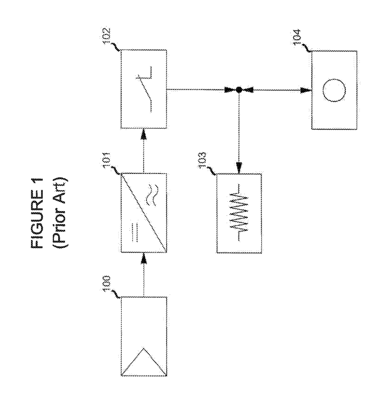
FIELD OF THE INVENTION[0001]The present invention relates to photovoltaic systems. In particular, it relates to photovoltaic systems for storing / drawing electricity in / from an accumulator.PRIOR ART[0002]Ever increasing energy needs require new forms of procurement, and to this end the most recent technological developments are focused on exploiting renewable resources naturally available to the best. With regards to the generation of electricity from natural sources, photovoltaic systems have been available for several years, allowing to transform solar energy into electricity.[0003]In general, as diagrammatically shown in FIG. 1, a photovoltaic system comprises at least one photovoltaic panel 100 exposed to solar radiation to receive solar energy and generate direct current electricity from solar energy. A network inverter 101, which converts the direct current generated by the solar panel 100 into alternating current, is connected to the output of the solar panel 100. The output o...

Claims


Application Information

Patent Timeline
Patent Type & Authority Patents(United States)
IPC IPC(8): H02J1/10H02J3/06H02J3/46H02J7/35H02J3/40H02J3/38H02J3/32
CPCH02J3/383H02J3/385H02J3/40H02J7/35Y02E10/58H02J3/32Y02E10/566H02J2300/26H02J3/381Y02E10/56Y02E70/30
Inventor OTTOLINI, DARIO
Owner OTTOLINI DARIO
Learn More