Fuel injection nozzle having multiple injection holes

a fuel injection nozzle and injection hole technology, which is applied in the direction of fuel injection apparatus, fuel feed system, combustion engine, etc., can solve the problems of short fuel spray tip length of the fuel jet, and insufficient mixing of fuel in the combustion chamber of the engine, etc., to achieve sufficient spray penetration of the fuel jet and sufficient atomization of fuel

Inactive Publication Date: 2007-04-10
DENSO CORP
View PDF12 Cites 12 Cited by
  • Summary
  • Abstract
  • Description
  • Claims
  • Application Information

AI Technical Summary

Benefits of technology

[0018]In the above nozzle, sufficient atomization of the fuel and sufficient spray penetration of the fuel jet are obtained. Thus, the spray tip length of the atomized fuel jet can be controlled so that the spray tip length is determined in accordance with the inner wall distance between the injection outlet and the inner wall of the combustion chamber.

Problems solved by technology

It is a main issue for the diesel engine to reduce generation of toxic substance in exhaust gas.
Thus, the air in the combustion chamber of the engine is not sufficiently mixed with the fuel jet.
However, in this nozzle, fuel concentration near the center of the fuel jet axis is increased, so that a part of the fuel jet having a high fuel concentration burns.
Thus, the fuel spray tip length of the fuel jet becomes short.
Accordingly, it is difficult to valance the spray penetration and the atomization.

Method used


Image

  • Fuel injection nozzle having multiple injection holes
  • Fuel injection nozzle having multiple injection holes
  • Fuel injection nozzle having multiple injection holes

Examples


Embodiment Construction

[0034]A fuel injection nozzle according to an example embodiment is shown in FIGS. 1 to 11. Firstly, outline of a construction of the nozzle is explained.

[0035]As shown in FIG. 11, the nozzle functions for jetting, i.e., spraying, a high pressure fuel into a cylinder of a diesel engine. The nozzle includes a nozzle body 1 and a needle 2. The nozzle is assembled in a nozzle holder (not shown), and the nozzle holder with the nozzle is mounted in the engine.

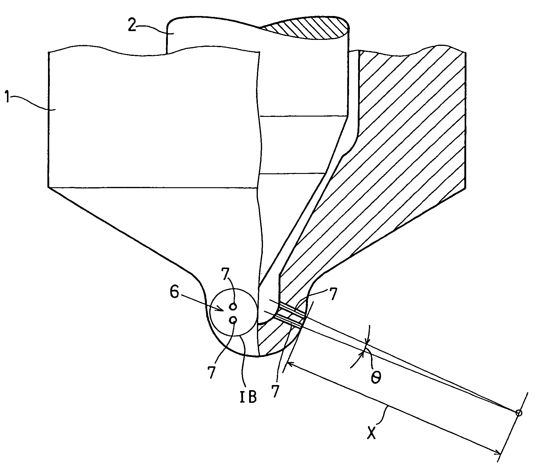
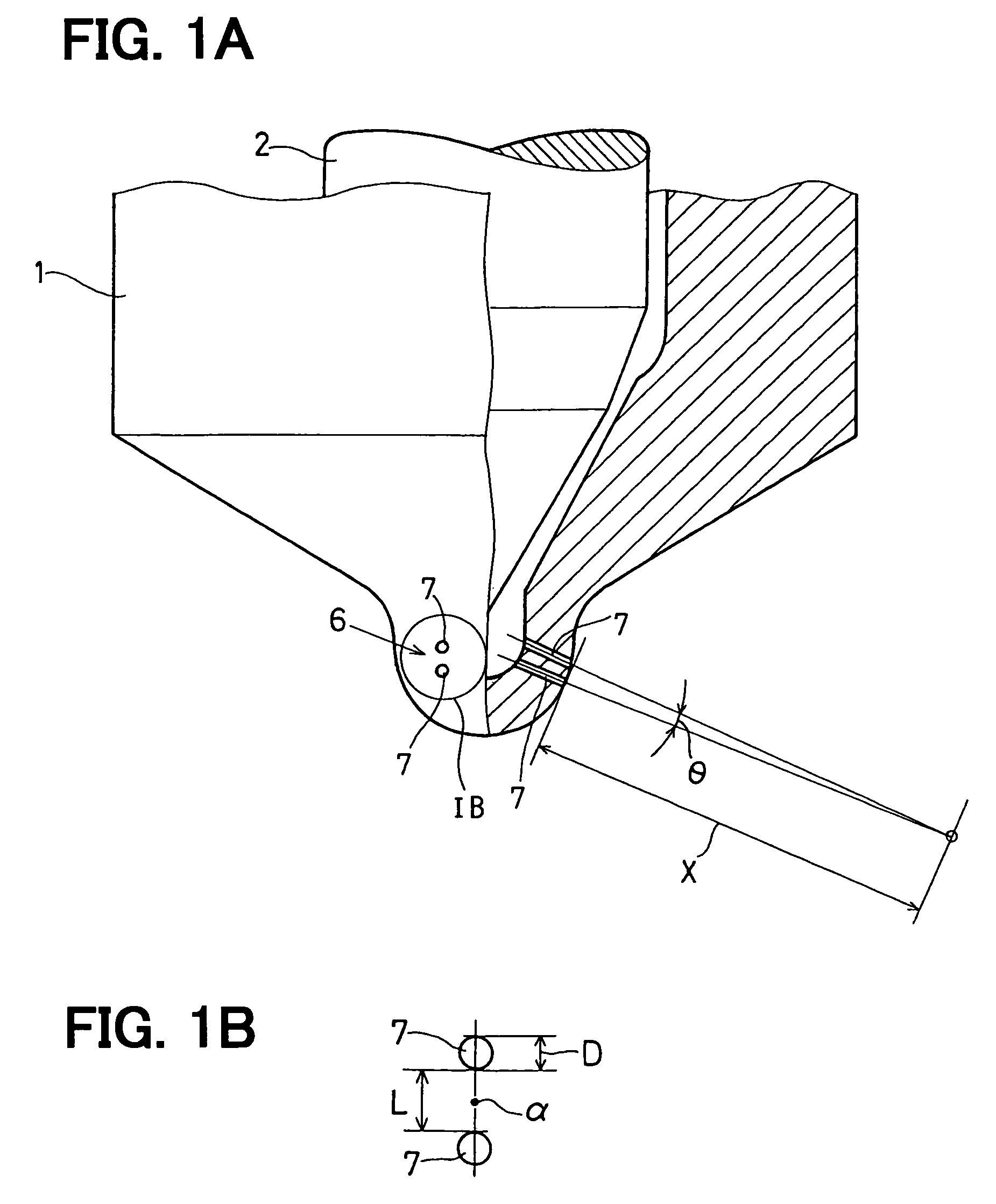
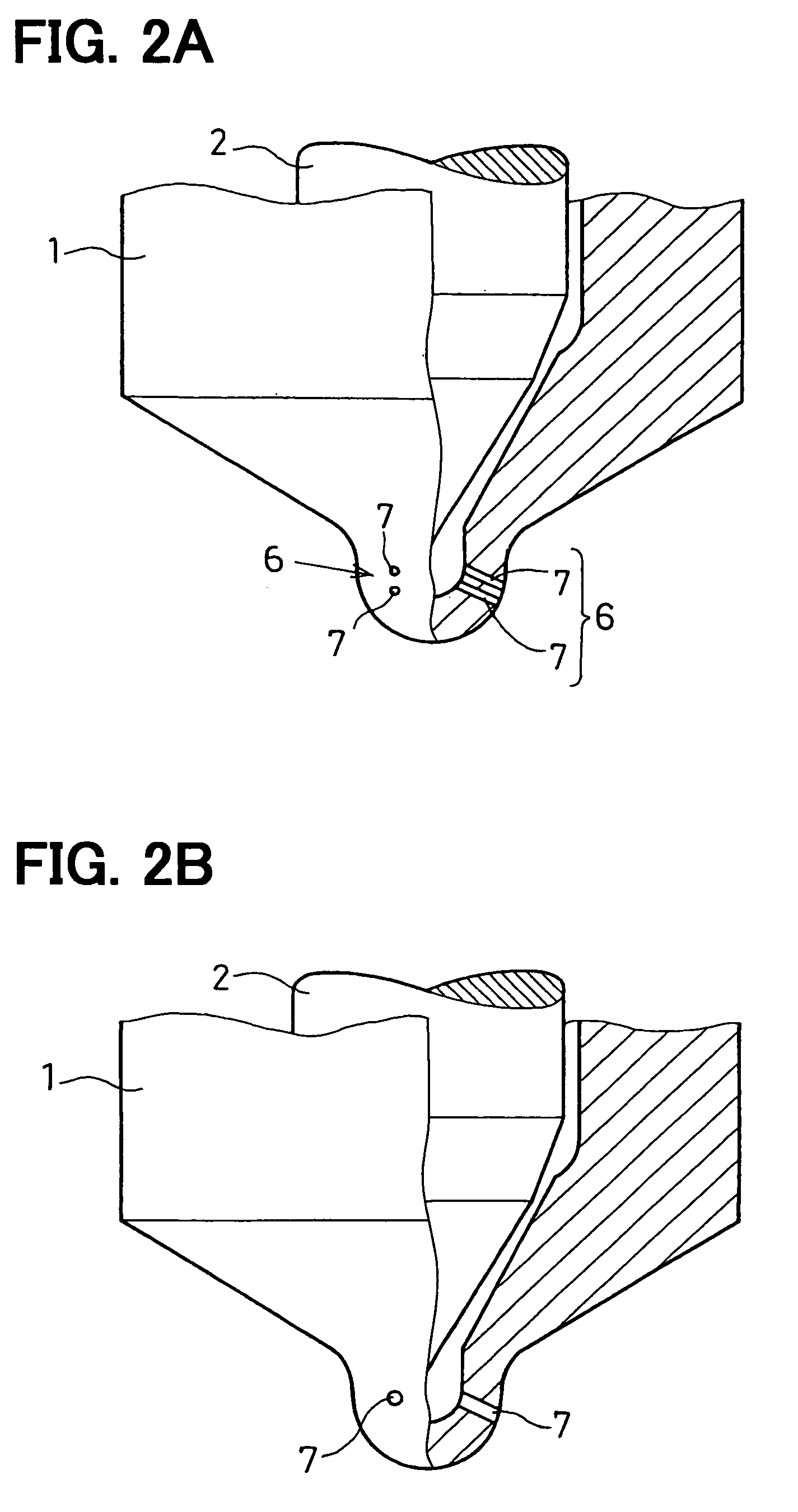
[0036]The nozzle body 1 includes a guide hole 3 for inserting the needle 2 therein, a fuel reservoir 4 disposed in a middle portion of the guide hole 3, a fuel introduction passage 5 connecting to the fuel reservoir 4, and an injection outlet 6 having multiple injection holes 7 for injecting the high pressure fuel into the cylinder of the engine. Multiple injection holes 7 provide the injection outlet 6, as shown in FIGS. 1A and 1B.

[0037]The guide hole 3 is formed from a top end of the nozzle body 1 to a bottom end of the nozzle bod...


PUM


Abstract

A fuel injection nozzle includes: an injection outlet having a plurality of injection holes. Each injection hole has an injection hole diameter defined as D, an outlet port and a center axis. The center axes of the injection holes cross at a cross point with a cross angle. A cross point distance between each outlet port of the injection holes and the cross point is defined as X. The cross angle of the center axes of the injection holes is defined as θ. The cross point distance X is in a range between 10 D and 100 D, and the cross angle θ is in a range between 1° and 10°.

Description

CROSS REFERENCE TO RELATED APPLICATION[0001]This application is based on Japanese Patent Application No. 2005-239117 filed on Aug. 19, 2005, the disclosure of which is incorporated herein by reference.FIELD OF THE INVENTION[0002]The present invention relates to a fuel injection nozzle having multiple injection holes.BACKGROUND OF THE INVENTION[0003]A diesel engine has a self-ignition system. Specifically, a fuel is introduced, i.e., supplied into a combustion chamber of the engine, and then, air with the fuel in the combustion chamber is compressed so that a temperature in the combustion chamber increases. Thus, the air with the fuel having high temperature is self-ignited. It is a main issue for the diesel engine to reduce generation of toxic substance in exhaust gas. Specifically, in order to perform combustion appropriately for reducing the toxic substance, atomization and spray penetration of the fuel, which is injected from a fuel injection nozzle, are much important for the di...

Claims


Application Information

Patent Timeline
Patent Type & Authority Patents(United States)
IPC IPC(8): B05B1/32
CPCF02M61/1813F02M61/182
Inventor SASAKI, SATORUKURONITA, TOKUJINAKAMURA, KANEHITO
Owner DENSO CORP
Why Eureka
Try Eureka