Frozen beverage blender

a beverage blender and blender technology, applied in the field of frozen beverage blenders, can solve the problems of increasing the cutting time of ice cubes, and increasing so as to reduce the cutting noise reduce the construction cost, and reduce the effect of ice cubes in operation

Inactive Publication Date: 2007-04-10
JOYTEC
View PDF8 Cites 5 Cited by
  • Summary
  • Abstract
  • Description
  • Claims
  • Application Information

AI Technical Summary

Benefits of technology

[0007]To solve the problems described above, a primary object of the present invention is to provide a frozen beverage blender equipped with an ice cutting mechanism capable of cutting ice cubes in a short period of time and decreasing the cutting noises of ice cubes in operation.
[0009]In the frozen beverage blender described above, the ice cubes falling from the chute are introduced into a space between the downwardly inclined conical inner surface of the upper hood and the downwardly inclined conical upper surface of the cutting disk and thrusted toward the cutting blade under the component of a centrifugal force caused by rotation of the rotary shaft. Thus, the ice cubes are sliced by the cutting blade positioned in the radial direction across the axis of the rotary shaft. This is effective to decrease cutting noises of the ice cubes in operation and to slice the ice cubes in a short period of time. With arrangement of a plurality of cutting blades about the rotary shaft, the cutting mechanism can be constructed small in size, and the ice cubes can be sliced in a more shorter period of time. In the case that the chute is inserted into the inlet opening formed in the cylindrical head portion of the upper hood to introduce the ice cubes falling from the ice storage container toward the rotary shaft, the ice cubes in the ice storage container can be prevented from rotation with the rotary shaft to further decrease cutting noises of the ice cubes in operation.
[0010]As in the frozen beverage blender, the cutting disk and lower hood are mounted to the lower end outer periphery of the upper hood by means of common screws, the cutting blade assembled with the cutting disk and the rotary plate can be removed downward in a simple manner for washing. In a practical embodiment of the present invention, it is preferable that the angle of the conical upper surface of the cutting disk relative to the conical inner surface of the upper hood is determined taking into account of the size of ice cubes stored in the ice storage container. Such arrangement of the angle is effective to increase the component of a centrifugal force acting on the ice cubes caused by rotation of the rotary shaft thereby to rapidly slice the ice cubes.

Problems solved by technology

In such operation of the cutting mechanism, cutting noises of the ice cubes become large.
The ice cubes falling on the axis center of the rotary plate causes the ice cubes in the container to rotate with the rotary plate, resulting in further increase of the cutting noises of ice cubes.
In the case that the conical casing is formed small in size to decrease the cutting noises of ice cubes, an amount of ice cubes sliced by the cutting blade per unit time is reduced, resulting an increase of cutting time of the ice cubes.
Accordingly, all the parts have to be removed from the upper portion of the cutting mechanism for washing, resulting in a trouble in washing of the parts.

Method used


Image

  • Frozen beverage blender
  • Frozen beverage blender
  • Frozen beverage blender

Examples


Embodiment Construction

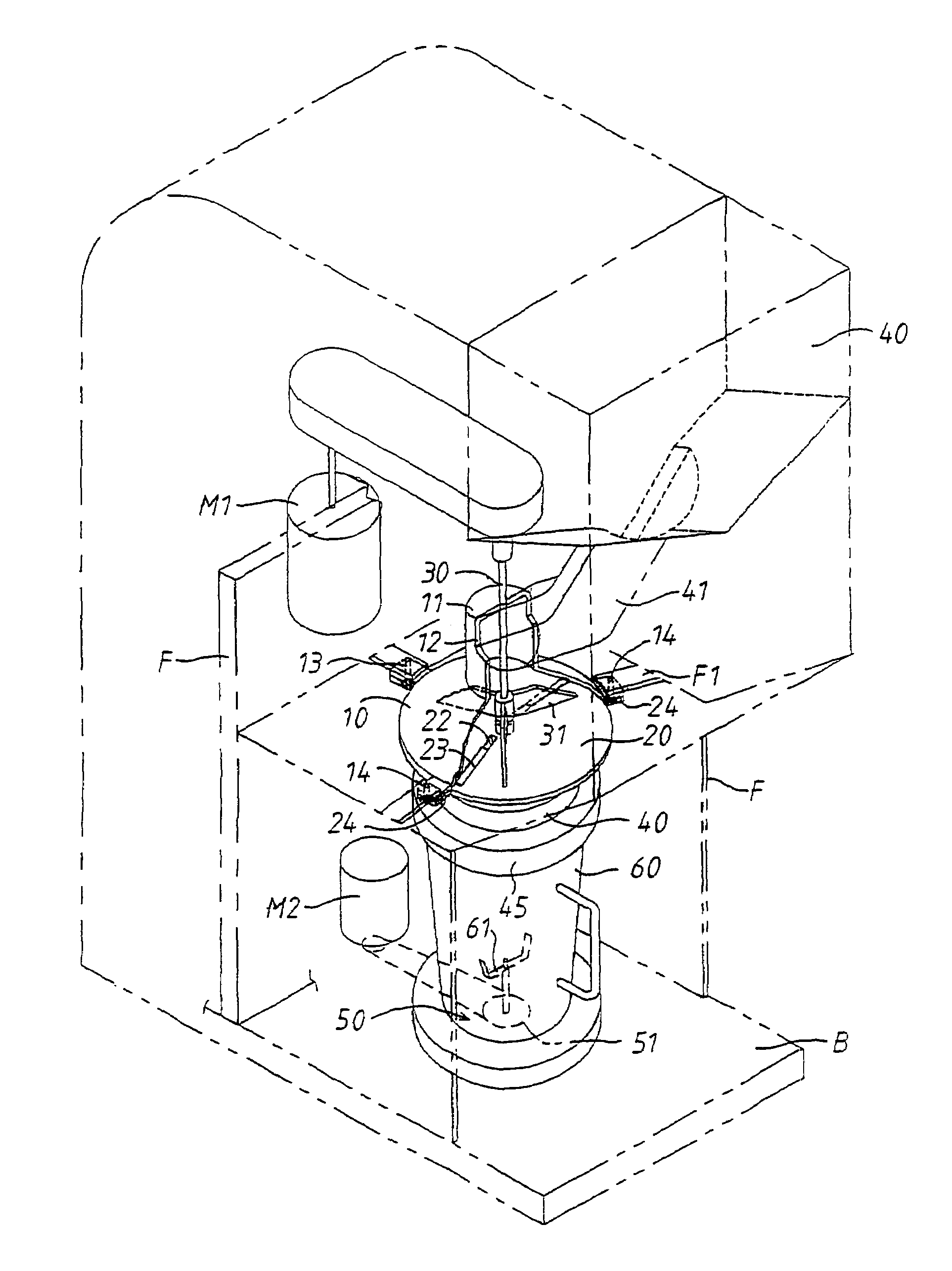
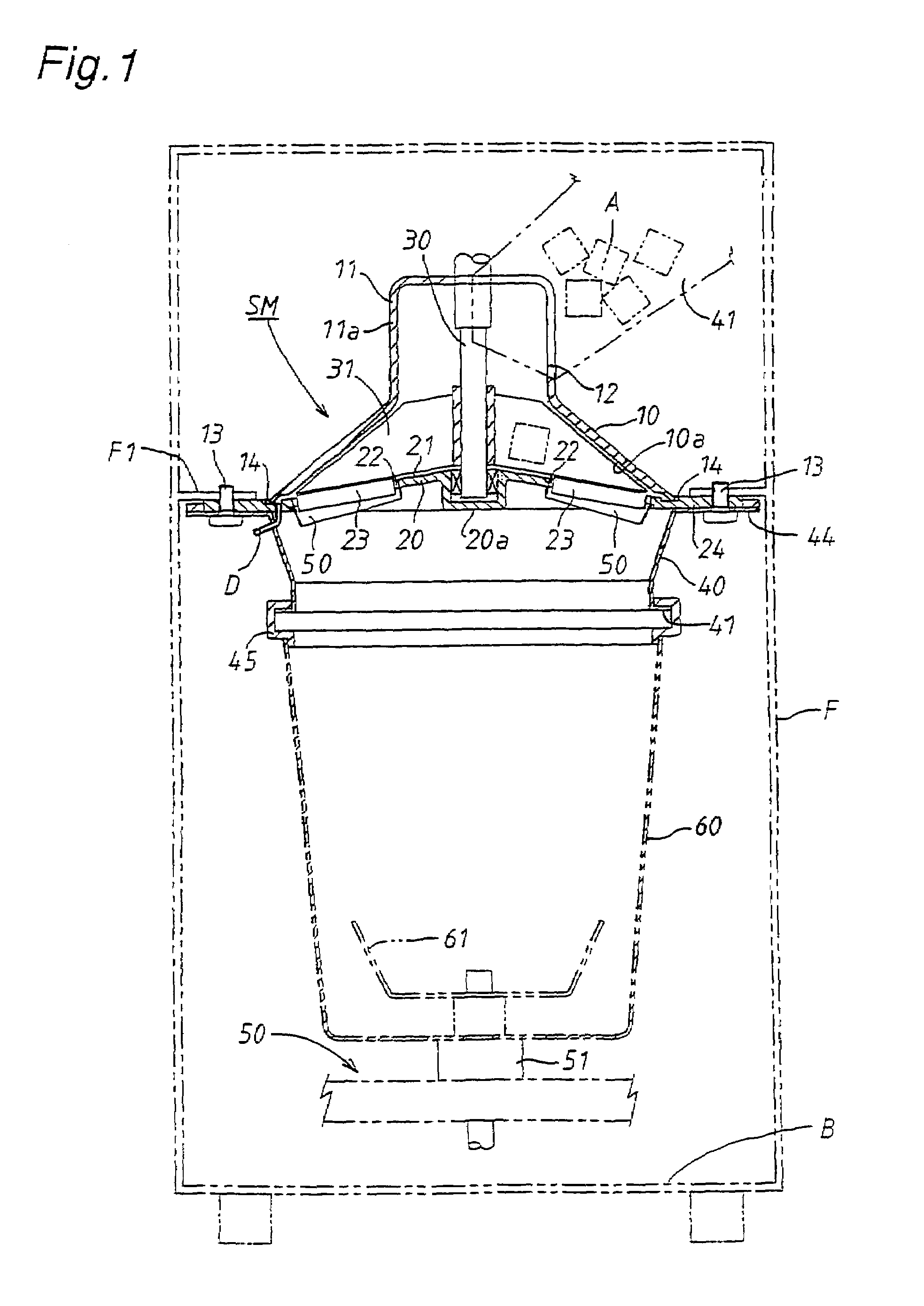
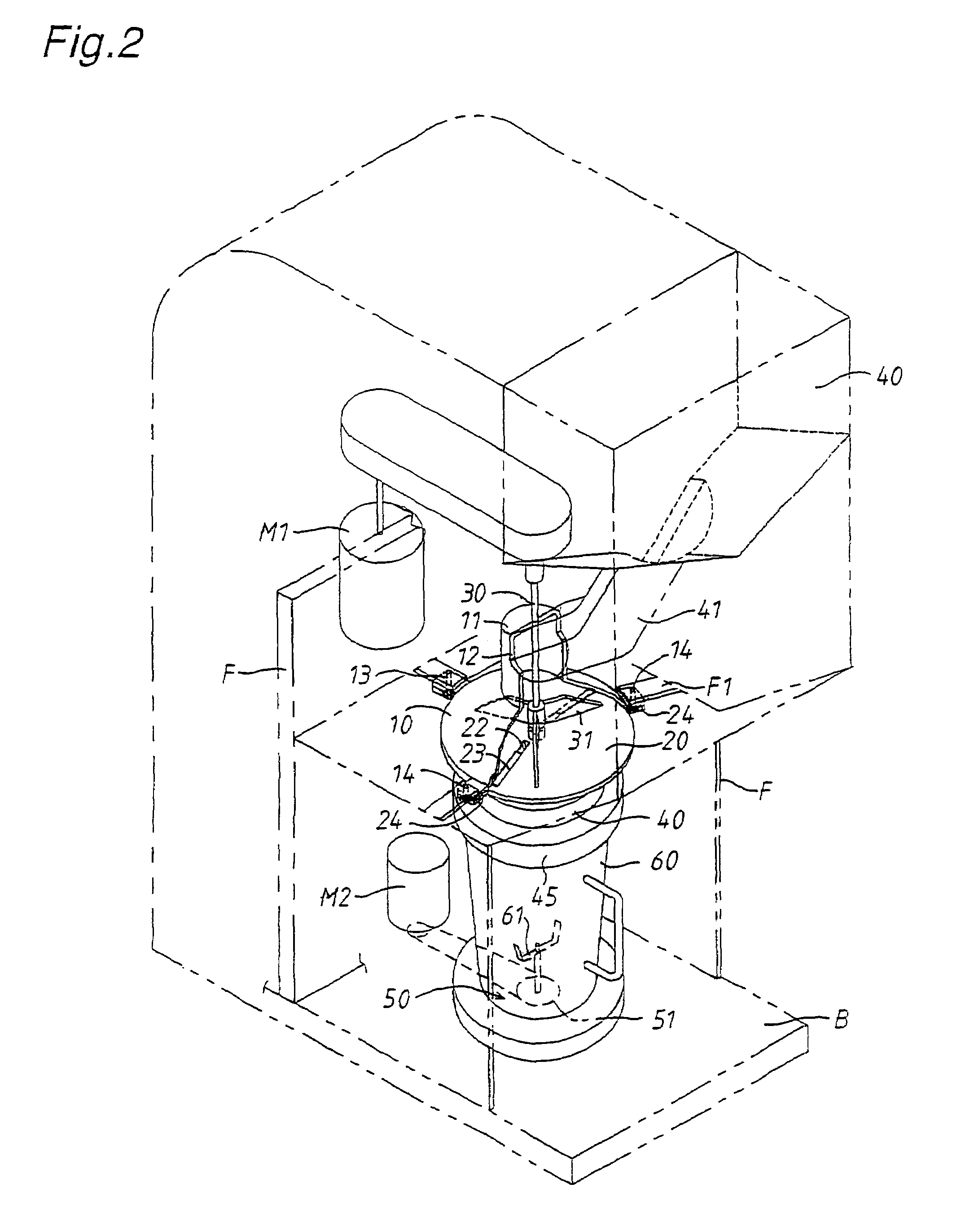
[0016]Illustrated in FIGS. 1 and 2 is a preferred embodiment of a frozen beverage blender equipped with an ice cutting mechanism in accordance with the present invention. The ice cutting mechanism in this embodiment includes an upright machine frame F mounted on a base structure B, an upper hood of aluminum die-casting horizontally mounted within the upright frame F to be removable downwardly, a cutting disk 20 of aluminum die-casting coupled at its lower end periphery with the lower end outer periphery of upper hood 10 to be removable downwardly, a rotary shaft 30 extended through the center of upper hood 10 and supported at its lower end on a boss portion formed on the head of cutting disk 20, and rotary plates 31 of aluminum die-casting driven by rotation of the rotary shaft 30 to rotate along the upper surface of cutting disk 20.

[0017]The upper hood 10 has a downwardly inclined conical inner surface 10a and a cylindrical head portion 11 formed at its peripheral wall 11a with an ...


PUM


Abstract

A frozen beverage blender equipped with an ice cutting mechanism including an upright machine frame mounted on a base structure, an upper hood horizontally mounted on the upper portion of the machine frame to be detachable downwardly, the upper hood having a downwardly inclined conical inner surface, a cutting disk coupled at its lower end outer periphery with a lower end outer periphery of the upper hood to be detachable downwardly, the cutting disk having a conical upper surface downwardly inclined from its center and being provided with a cutting blade mounted thereon in such a manner that the edge of the cutting blade is positioned upward at a radial slit formed in the cutting disk, a rotary shaft vertically extending through the center of the upper hood and being supported at its lower end on the head of the cutting disk, and a rotary plate driven by the rotary shaft to rotate along the upper surface of the cutting disk, wherein the upper hood has a cylindrical head portion formed with an inlet opening for introducing ice cubes falling from an ice storage container located above the machine frame.

Description

BACKGROUND OF THE INVENTION[0001]1. Field of the Invention[0002]The present invention relates to a frozen beverage blender equipped with a cutting mechanism of ice cubes.[0003]2. Description of the Prior Art[0004]As is disclose in Japanese Utility Model Registration No. 252637, a cutting mechanism of this kind adapted for use in a frozen beverage blender is composed of an ice storage container placed above a conical casing, a cutting blade mounted on an upwardly inclined peripheral wall of the conical casing, a rotary plate driven by rotation of a rotary shaft to rotate along the inner surface of the conical casing, and a chute arranged at a front side of a beverage blender to introduce ice cubes falling from the ice storage container and drop ice pieces sliced by the cutting blade just under the cutting blade.[0005]In the cutting mechanism described above, a large amount of ice cubes dropped in the conical casing are moved upward along the inner wall of the conical casing under a c...

Claims


Application Information

Patent Timeline
Patent Type & Authority Patents(United States)
IPC IPC(8): B02C17/02B07B13/00A47J43/042A47J43/046
CPCA47J43/042A47J43/046Y10S241/17F25C5/12
Inventor NAKATO, YUTAKASUZUKI, KAORUKOBAYASHI, NORIYUKI
Owner JOYTEC
Why Eureka
Try Eureka