
Backlighting method for an automotive trim panel

a technology for automotive trim panels and backlighting, which is applied in the direction of emergency actuators, light support devices, legends, etc., can solve the problems of not being able to observe holes to a person of normal vision, unable to teach the use of formed openings as illumination light pipes, and expensive assembly,

Inactive Publication Date: 2007-04-10
LISA DRAXLMAIER GMBH
View PDF54 Cites 72 Cited by
  • Summary
  • Abstract
  • Description
  • Claims
  • Application Information

AI Technical Summary

Problems solved by technology

These assemblies are expensive to fabricate, stock, and assemble.
These holes are not observable to a person of normal vision when viewed from the passenger compartment.
Although these references teach forming openings in an vehicle instrument panel with a laser, they fail to teach locating a light source behind the openings and using the formed openings as illumination light pipes.

Method used


Image

  • Backlighting method for an automotive trim panel
  • Backlighting method for an automotive trim panel
  • Backlighting method for an automotive trim panel

Examples


Embodiment Construction

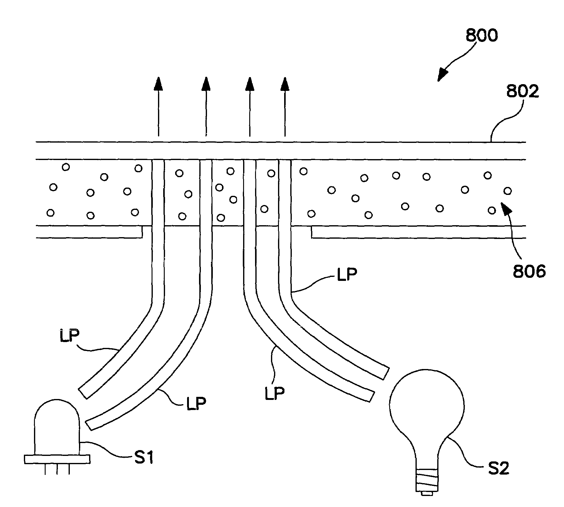
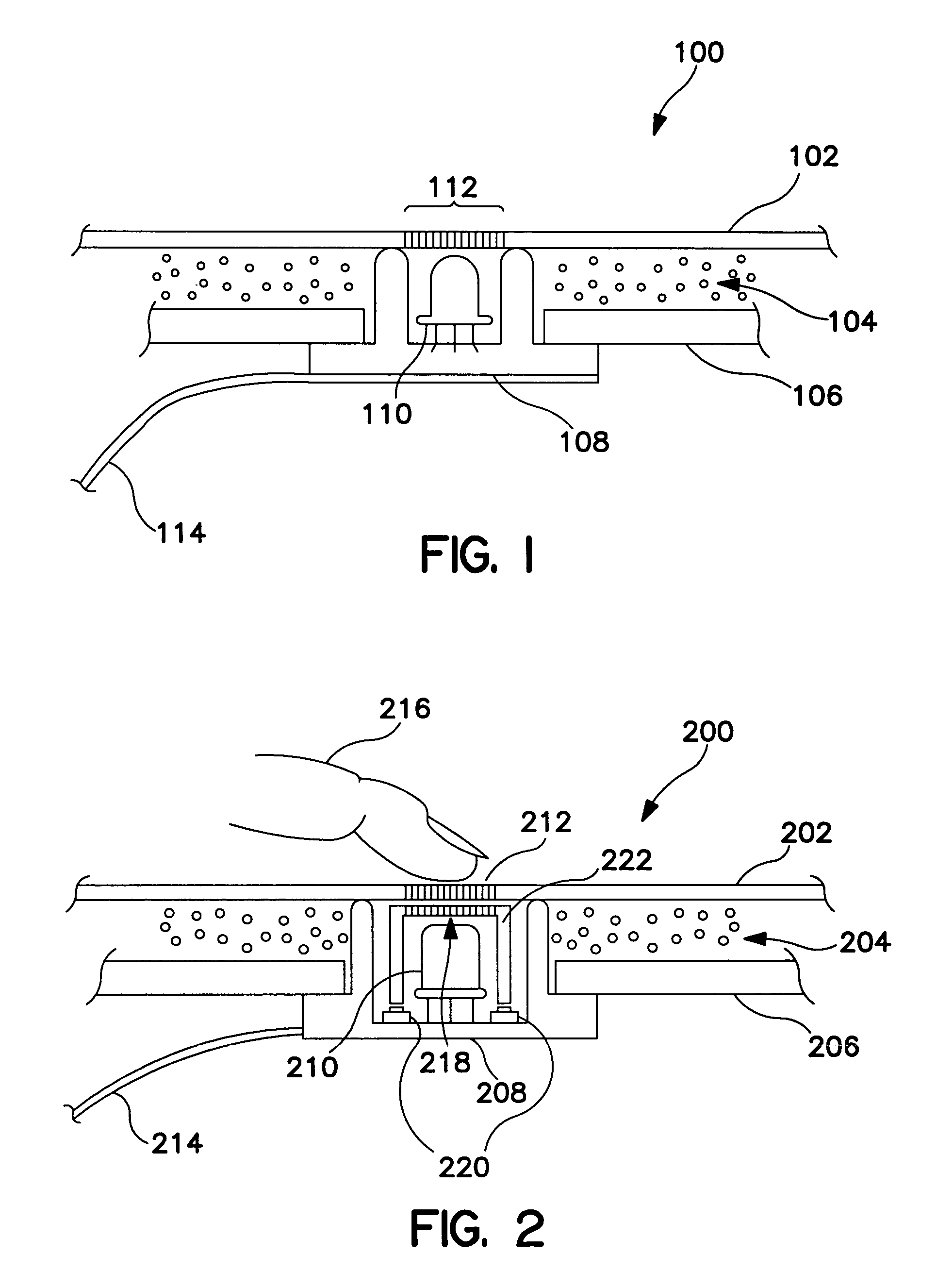
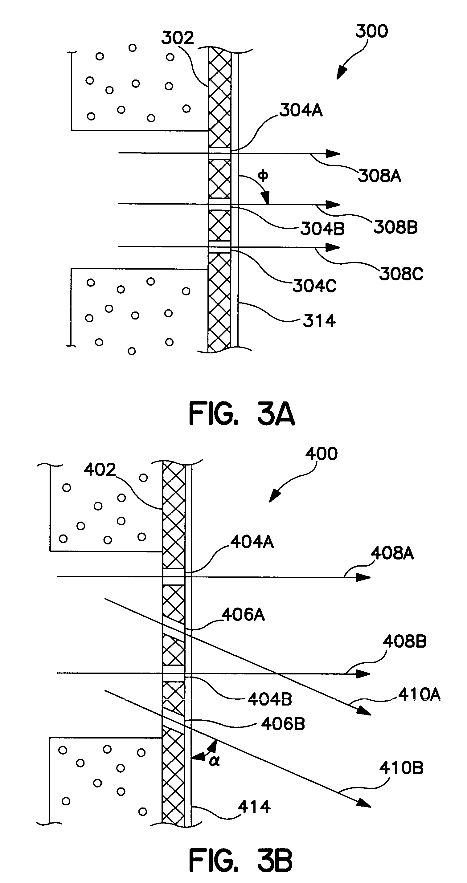
[0020]Referring to the drawings, there is illustrated generally at 100, a profile view of a first embodiment backlit automotive trim panel in accordance with the present invention. An automotive trim panel 100 may include, but is not limited to, an automotive instrument panel, door panels, headliners, and consoles. The trim panel 100 has a cover layer 102, a cushion / foam layer 104, and a retainer layer 106. The cover layer 102 may be made of leather, vinyl (PVC), polyurethane, a textile such as cloth, or other pliable materials. By the term pliable it is meant that the cover layer is flexible at room temperature in the sense that it will deflect and will be capable of recovery when used as a cover layer in an automotive trim panel application. More specifically, the surface of the cover layer has a surface that will deflect upon contact pressure typical within the automobile environment. In that regard, an alternative definition of the term pliable, therefore, would apply to those p...


PUM


Abstract

The present invention relates to an apparatus and method of perforating the cover layer or soft skin of an automotive trim panel such as an instrument panel with a laser to allow light to bleed through the perforations. The light source would preferably be a low heat generating or “cool” type source such as an LED. The light source would be attached to a suitable substrate or incorporated in to a flexible printed circuit and coupled to the vehicle electrical system. This method would enable fill switch integration to a trim panel and provide a seamless styling opportunity regarding the electrical controls. This method would help reduce cost and weight, improve quality, and promote new seamless styling theme.

Description

CROSS-REFERENCE TO RELATED APPLICATIONS[0001]This application is a divisional application of U.S. application Ser. No. 09 / 773,840, filed Jan. 31, 2001, now U.S. Pat. No. 6,652,128.FIELD OF THE INVENTION[0002]The present invention relates to an apparatus and method of back lighting an automotive trim panel, particularly an instrument panel, by perforating the cover layer with a laser and locating a light source there behind. The perforations allowing light from a low heat generating or “cool” type light source such as an LED to bleed through the perforations so as to be seen by the vehicle occupant.BACKGROUND OF THE INVENTION[0003]Currently, automotive interior back lighting requires a bezel or other plastic piece and a light source. The bezel is attached to a trim panel such as an instrument panel, console, or door panel. The light source is typically used to backlight a switch or knob. The bezel mounts in an opening in the trim panel and a portion of the bezel rests on top of the t...

Claims


Application Information

Patent Timeline
IPC IPC(8): G09F13/00B60Q3/00B60Q3/02B60Q3/04F21V8/00
CPCB60K37/06B60Q3/005B60Q3/0283B60Q3/044G02B6/0008B60K2350/2039H01H2009/187H01H2219/058H01H2219/062H01H2221/084H01H2231/026B60Q3/66B60Q3/745B60Q3/14B60K35/10B60K2360/34
Inventor MISARAS, DAVID M.
Owner LISA DRAXLMAIER GMBH
Learn More