Semiconductor radiological detector and semiconductor radiological imaging apparatus
a radiological detector and semiconductor technology, applied in the direction of instruments, radiation controlled devices, optical radiation measurement, etc., can solve the problems of detector decline, sensitivity, spatial resolution, detector dead space, etc., to prevent the dead space of the signal line, improve detection sensitivity, and prevent the effect of signal line dead spa
- Summary
- Abstract
- Description
- Claims
- Application Information
AI Technical Summary
Benefits of technology
Problems solved by technology
Method used
Image
Examples
first embodiment
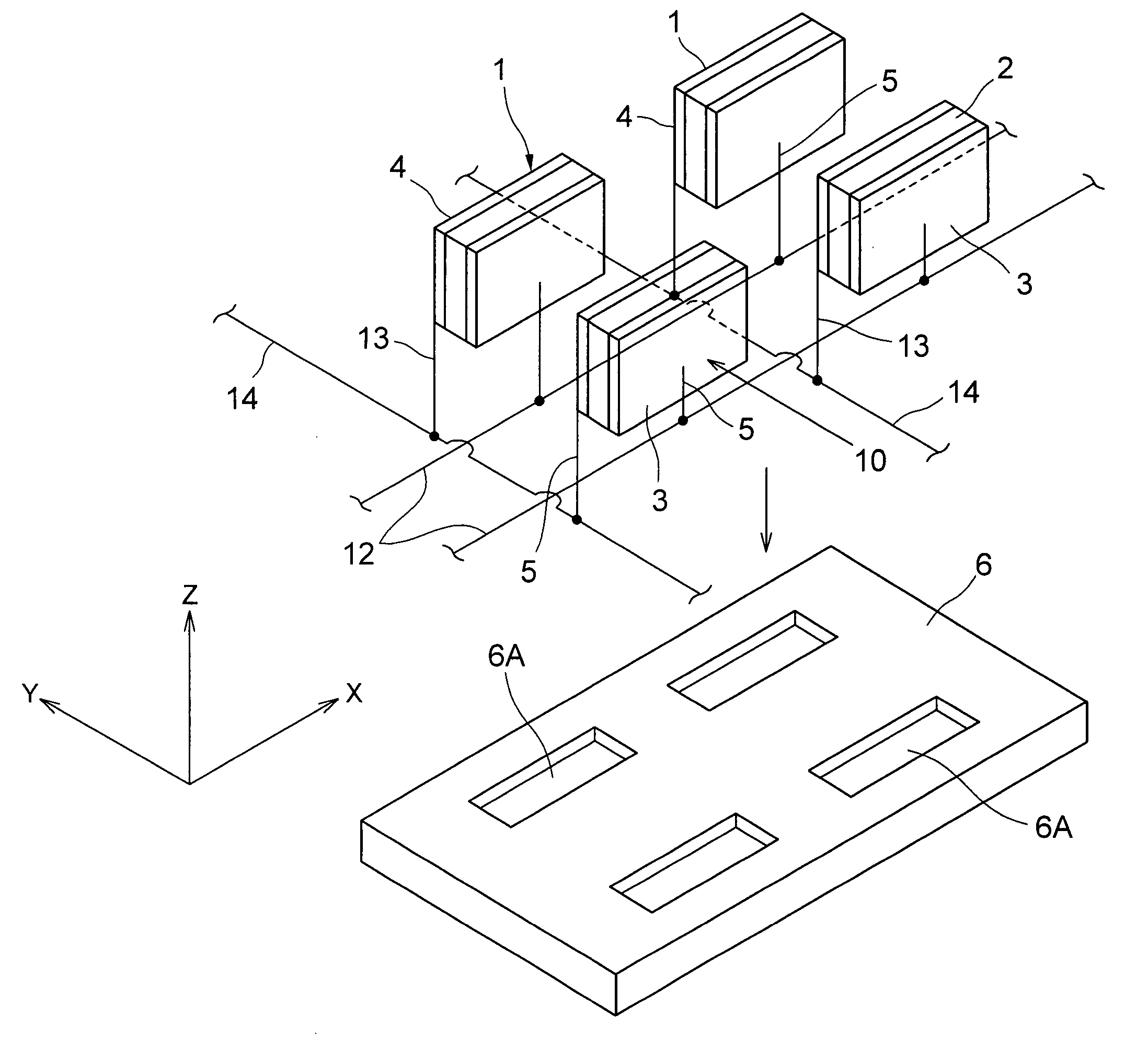
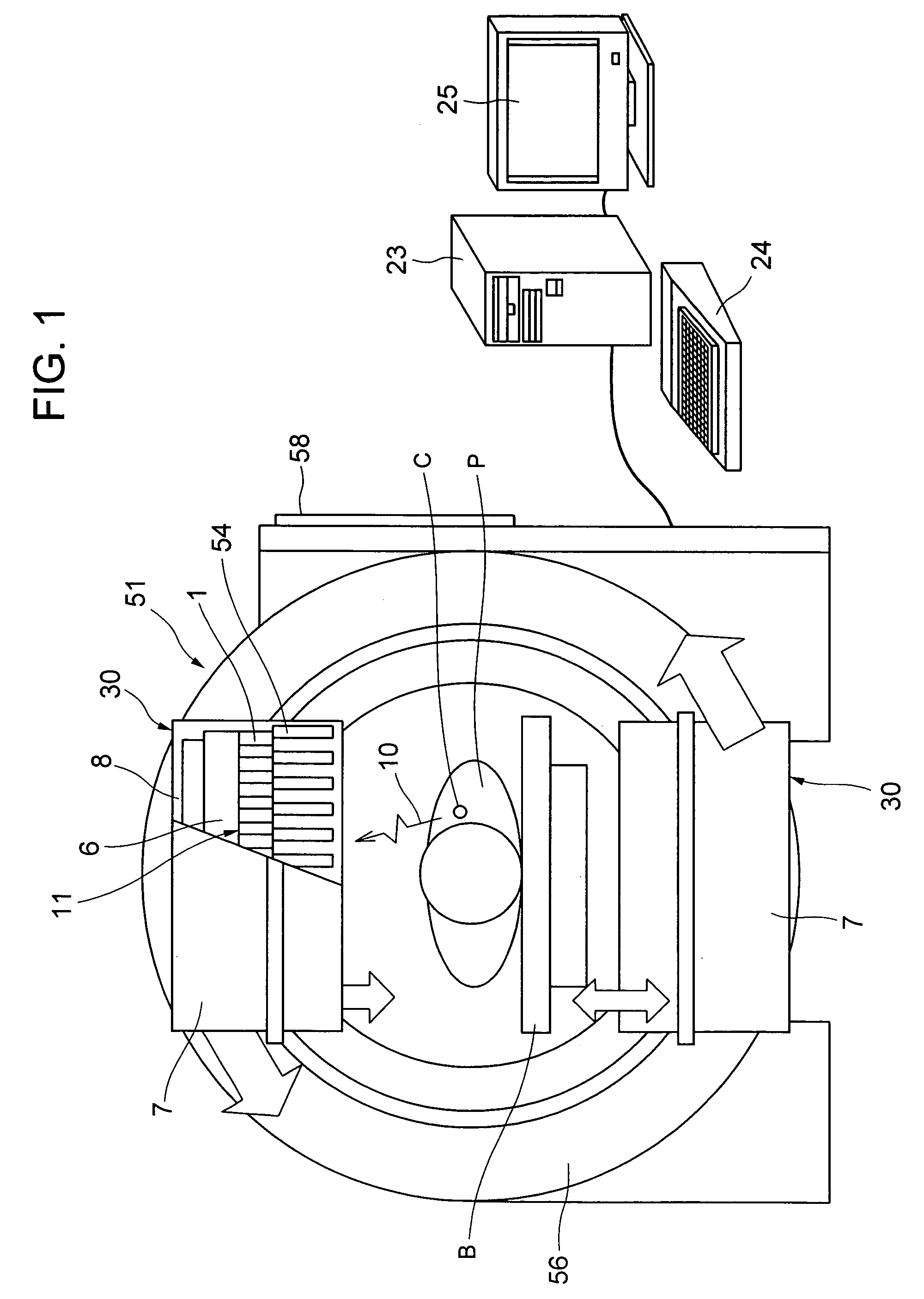
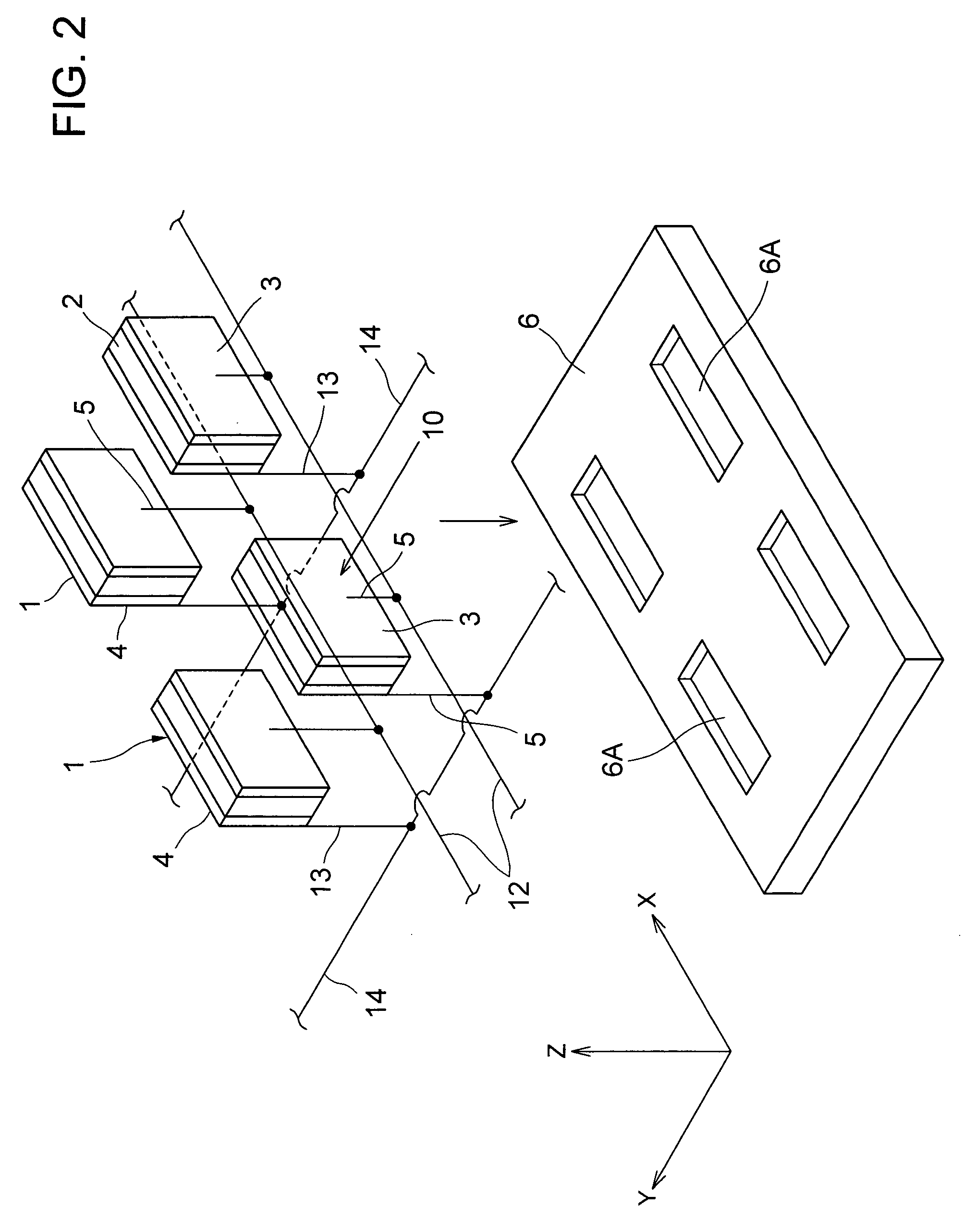
[0020]A first embodiment of the present invention will be described below with reference to FIGS. 1 and 2, which are accompanying drawings.
[0021]In FIG. 1, a SPECT (Single Photon Emission Computer Tomography) apparatus 51 that is a radiological imaging apparatus comprises paired semiconductor radiological detecting apparatuses 30, a rotating support table 56, a data collecting and analyzing apparatus 23, a data input apparatus 24, and a display apparatus 25. Paired semiconductor radiological detecting apparatuses 30 are arranged on the rotating support table 56 at an angle of 180° to each other in a circumferential direction. Specifically, socket board mounting substrates 6 of the semiconductor radiological detecting apparatuses 30 are mounted on the rotating support table 56 at an angle of 180° to each other in the circumferential direction. Each radiological detecting unit 11 faces a bed B. A collimator 54 is installed between the radiological detecting unit 11 and a patient P to ...
second embodiment
[0031]Now, with reference to FIG. 3, description will be given of a second embodiment of the present invention.
[0032]In FIG. 3, a radiological detecting unit 60 comprises a plurality of semiconductor radiological detectors 61, 61, . . . (only four are shown) as in the case of the first embodiment. That is, if the thickness of a single semiconductor device 61 is simply increased, the distance between electrodes, in other words, a charge collection distance increases to reduce the energy resolution. However, in the present embodiment, a plurality of semiconductor radiological detectors 1 are arranged parallel to one another with the inter-electrode distance of a single device reduced. This provides a semiconductor radiological detector 1 having both high energy resolution and high detection efficiency. The semiconductor radiological detector 61 has two semiconductor devices 62, 62 arranged opposite each other, anodes 63, 63 placed between the semiconductor devices 62 and 62, and catho...
third embodiment
[0036]Now, a third embodiment of the present invention will be described with reference to FIGS. 4 and 7.
[0037]In FIG. 4, a radiological detecting unit 70 comprises a plurality of semiconductor radiological detectors 71, 71, . . . (only six of them are shown). The semiconductor radiological detector 71 is composed of two semiconductor devices 72A and 72B arranged opposite each other, anodes 73A and 73B placed between the semiconductor devices 72A and 72B, cathodes 74A and 74B placed opposite the anodes 73A and 73B via the semiconductor devices 72A and 72B, respectively, and a protective connector case 75 that accommodates the semiconductor devices 72A and 72B, the cathodes 73A and 73B, and the anodes 74A and 74B. A bottom part of the protective connector case 75 is provided with a cathode pin 76 that is a signal line connected to the cathodes 73A and 73B and an anode pin 77 that is another signal line connected to the anodes 74A and 74B. Further, a socket board 78 is formed with a c...
PUM
 Abstract
Description
Claims
Application Information
 - R&D
- Intellectual Property
- Life Sciences
- Materials
- Tech Scout
- Unparalleled Data Quality
- Higher Quality Content
- 60% Fewer Hallucinations
Browse by: Latest US Patents, China's latest patents, Technical Efficacy Thesaurus, Application Domain, Technology Topic, Popular Technical Reports.
© 2025 PatSnap. All rights reserved.Legal|Privacy policy|Modern Slavery Act Transparency Statement|Sitemap|About US| Contact US: help@patsnap.com


