Method for controlling an electric motor to reduce EMI

a technology of electric motors and motors, applied in the direction of motor/generator/converter stoppers, dynamo-electric converter control, ac motor stoppers, etc., can solve the problems of excessive heating and loss of voltage applied to the motor, and brushless dc motor drives produce significant amounts of electromagnetic interference, so as to increase the output torque and increase the rotary speed, without drastic changes in the design of the motor or the design of the system

Inactive Publication Date: 2007-04-10
INFINEON TECH AMERICAS CORP
View PDF43 Cites 64 Cited by
  • Summary
  • Abstract
  • Description
  • Claims
  • Application Information

AI Technical Summary

Benefits of technology

[0020]A problem solved by the present invention is the reduction of EMI by the motor controller. According to the invention, conduction angle control of a brushless DC motor reduces the number of switching events in the power stage, thereby reducing the amount of electromagnetic emissions. This allows the use of smaller, lower cost EMI filtering components and allows the controller to meet regulation requirements.

Problems solved by technology

Brushless DC motor drives produce significant amounts of electromagnetic interference due to the switching voltages and current involved.
High resistance results in excessive heating and loss of voltage applied to the motor.

Method used


Image

  • Method for controlling an electric motor to reduce EMI
  • Method for controlling an electric motor to reduce EMI
  • Method for controlling an electric motor to reduce EMI

Examples


Embodiment Construction

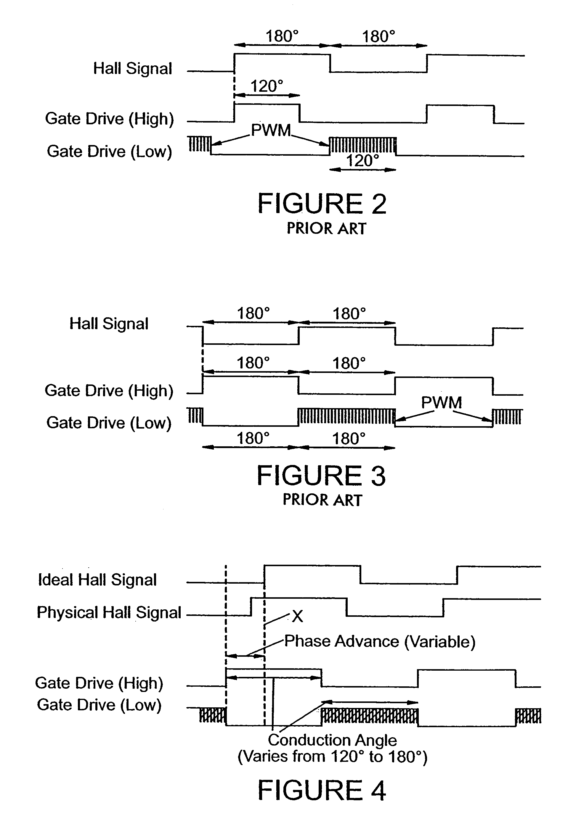
[0055]Turning now to FIG. 4, this figure shows gate drive high and gate drive low signals for one motor phase, as well as the ideal and physical Hall signals from the motor. The ideal Hall signal is placed such that if 120° conduction angle were used with 0° phase advance, the switching instants would occur at the same time as the Hall signal transitions. This is shown in FIG. 4 by the dashed line x. If no phase advance is provided, the switching instants for the high drive signal would coincide with the rising edge of the ideal Hall signal. The physical Hall signal may be offset (advanced) from the ideal Hall signal by some amount, which can be 0°, or some value greater than 0°. An exemplary physical Hall signal is shown in FIG. 4. The variable phase advance (from the ideal Hall signal) is indicated in FIG. 4. FIG. 4 shows that the gate drive high signal is switched on some variable phase amount prior to the ideal Hall transition and some variable amount prior to the physical Hall ...


PUM


Abstract

A method for reducing EMI emissions in the control of an electric motor supplied by a switching inverter fed by a DC bus comprising controlling a phase advance of a conduction angle period during which a phase of the motor is fed power by the inverter to control the conduction angle to control the speed of the motor, thereby to reduce the number of switching operations of the inverter and thereby reduce EMI.

Description

CROSS REFERENCE TO RELATED APPLICATIONS[0001]This application claims the benefit and priority of U.S. Provisional Application No. 60 / 578,511 filed Jun. 10, 2004 and entitled CONDUCTION ANGLE CONTROL REDUCES EMI and further is a continuation-in-part of U.S. application Ser. No. 10 / 425,091 entitled ELECTRONICALLY CONTROLLED POWER STEERING SYSTEM FOR VEHICLE AND METHOD AND SYSTEM FOR MOTOR CONTROL, filed Apr. 28, 2003, now U.S. Pat. No. 6,995,679 which application claims the priority and benefit of U.S. Provisional Application No. 60 / 377,296 filed May 1, 2002, and entitled ELECTRONICALLY CONTROLLED POWER STEERING SYSTEM FOR VEHICLE, and U.S. Provisional Application No. 60 / 376,617 filed Apr. 30, 2002 and entitled SYSTEM AND METHOD FOR CONTROLLING ELECTRIC MOTOR WITH VARIABLE PHASE ADVANCE / CONDUCTION ANGLE the entire disclosures of each of which are incorporated herein by reference.BACKGROUND OF THE INVENTION[0002]1. Field of the Invention[0003]The present invention relates to electrical...

Claims


Application Information

Patent Timeline
Patent Type & Authority Patents(United States)
IPC IPC(8): H02P1/18H02K23/16H02M1/12H02M1/44H02M7/5387H02P23/00H02P23/04H02P29/00
CPCB62D5/065H02M1/44H02M7/53875H02P23/0081H02P23/04H02P29/0038H02M1/12H02P23/26H02P29/50
Inventor ESKRITT, JAMES BKUEHNER, JOEL E
Owner INFINEON TECH AMERICAS CORP
Why Eureka
Try Eureka