Flame detection system

a detection system and flame technology, applied in fire alarms, optical radiation measurement, instruments, etc., can solve problems such as false alarms of flame detectors

Active Publication Date: 2007-04-10
MSA TECH
View PDF34 Cites 68 Cited by
  • Summary
  • Abstract
  • Description
  • Claims
  • Application Information

AI Technical Summary

Benefits of technology

[0002]Some flame detectors may use a single sensor, for an optical sensor, which operates at one of the spectral regions characteristic of radiation from flames. Flame detectors may measure the total radiation corresponding to the entire field of view of the sensor and measure radiation emitted by all sources of radiation in the spectral range being sensed within that field of view, including flame and / or non-flame sources which may be present. A flame detector may produce a “flame” alarm, intended to indicate the detection of a flame, when the level of combined radiation sensed reaches a predetermined threshold level, known or thought to be indicative of a flame.

Problems solved by technology

Some flame detectors may produce false alarms which can be caused by an instrument's inability to distinguish between radiation emitted by flames and that emitted by other sources such as incandescent lamps, heaters, arc welding, or other sources of optical radiation.

Method used


Image

  • Flame detection system
  • Flame detection system
  • Flame detection system

Examples


Embodiment Construction

[0017]In the following detailed description and in the several figures of the drawing, like elements are identified with like reference numerals.

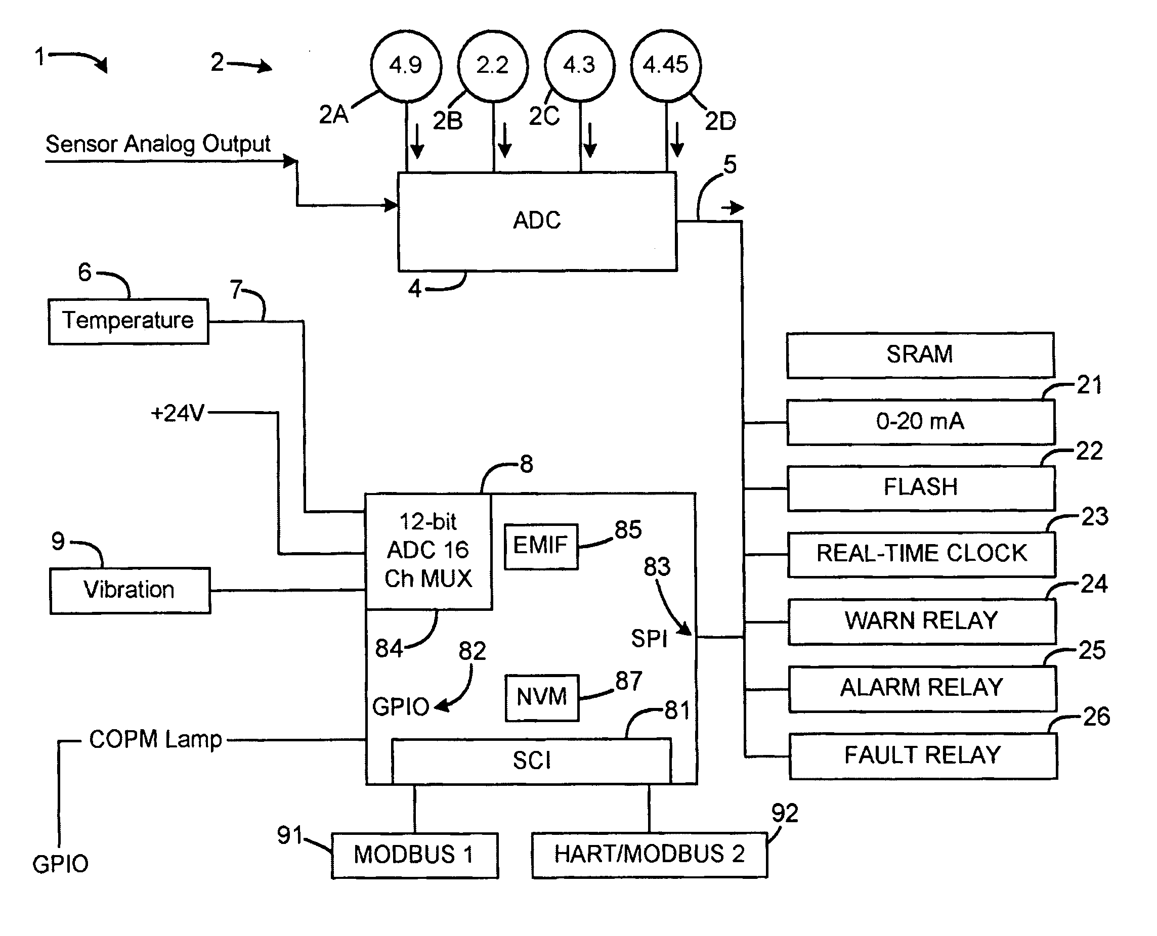
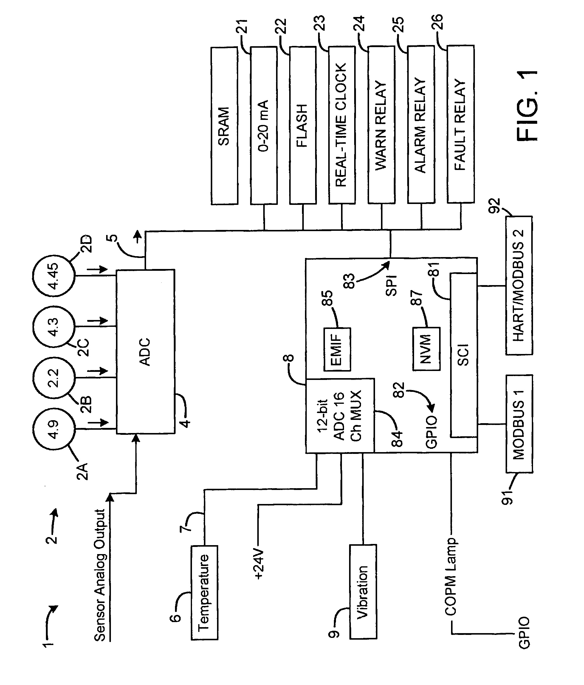
[0018]FIG. 1 illustrates a schematic block diagram of an exemplary flame detector system 1 comprising a plurality of detectors 2 responsive to optical radiation to generate a plurality of respective analog detector signals 3. An analog-digital converter (ADC) 4 converts the analog detector signals 3 into digital detector signals 5. In an exemplary embodiment, the ADC 4 provides 24-bit resolution.

[0019]In an exemplary embodiment, the flame detector system 1 includes an electronic controller 8, e.g., a digital signal processor (DSP) 8, an ASIC or a microcomputer or microprocessor based system. In an exemplary embodiment, the signal processor 8 may comprise a Texas Instruments F2812 DSP, although other devices or logic circuits may alternatively be employed for other applications and embodiments. In an exemplary embodiment, the signal processo...


PUM


Abstract

A flame detection system includes a plurality of sensors for generating a plurality of respective sensor signals. The plurality of sensors includes a set of discrete optical radiation sensors responsive to flame as well as non-flame emissions. An Artificial Neural Network may be applied in processing the sensor signals to provide an output corresponding to a flame condition.

Description

BACKGROUND OF THE DISCLOSURE[0001]Flame detectors may comprise an optical sensor for detecting electromagnetic radiation, for example, visible, infrared or ultraviolet, which is indicative of the presence of a flame. A flame detector may detect and measure infrared (IR) radiation, for example in the optical spectrum at around 4.3 microns, a wavelength that is characteristic of the spectral emission peak of carbon dioxide. An optical sensor may also detect radiation in an ultraviolet range at about 200–260 nanometers. This is a region where flames have strong radiation, but where ultra-violet energy of the sun is sufficiently filtered by the atmosphere so as not to prohibit the construction of a practical field instrument.[0002]Some flame detectors may use a single sensor, for an optical sensor, which operates at one of the spectral regions characteristic of radiation from flames. Flame detectors may measure the total radiation corresponding to the entire field of view of the sensor ...

Claims


Application Information

Patent Timeline
Patent Type & Authority Patents(United States)
IPC IPC(8): G08B17/12G01J5/06G08B17/10G08B29/26G08B31/00
CPCG08B17/10G08B31/00G08B29/26G08B17/12
Inventor HUSEYNOV, JAVID J.BALIGA, SHANKARSHUBINSKY, GARY D.BOGER, ZVI
Owner MSA TECH
Why Eureka
Try Eureka