Check patentability & draft patents in minutes with Patsnap Eureka AI!

High strength bolted structure and method of securing nut and torque-shear type high strength bolt and joining method using same

Inactive Publication Date: 2007-04-17
NIPPON STEEL CORP +1
View PDF57 Cites 32 Cited by
  • Summary
  • Abstract
  • Description
  • Claims
  • Application Information

AI Technical Summary

Benefits of technology

[0032](15) A Torque-Shear type high strength bolt as set forth in (13) or (14), characterized in that at least the head seat face and thread of the bolt are lubricated.
[0033](16) A Torque-Shear type high strength bolt as set forth in (13) or (14), characterized in that a bolt head side seat face of a washer inserted and abutted between a head seat face of the bolt and a steel member to be joined is lubricated.
[0034](17) A Torque-Shear type high strength bolt as set forth in (13) or (14), characterized in that at least a head seat face and thread of the bolt are lubricated and a bolt head side seat face of a washer inserted and abutted between a head seat face of the bolt and a steel member to be joined is lubricated.
[0035](18) A bolting method of a steel member using a Torque-Shear type high strength bolt as set forth in any one of (13) to (17) formed at the front end of its head with a pintail for torque control and formed between the head and the pintail with a breakneck comprised of a breaking groove, said bolting method using a Torque-Shear type high strength bolt characterized by, when screwing

Problems solved by technology

In such a through diaphragm type join structure, the compressive force and tension at the upper and lower flanges occurring when a bending moment acts on the H-section beam can be transmitted to the box section column without causing a reduction in the rigidity of the join, but the structure is complicated and the number of processing steps becomes huge.
Such a large projection obstructs application of fire-resistant coverings and finishing work.
Further, in the case of naked frames, it impair the aesthetic appearance and therefore is not preferable in terms of design either.
Further, in such a join structure of a box section column and split T-section, the bolting work is impossible with usual bolting using a general high strength bolt (for example, high strength hexagonal bolt for friction grip joins as defined in JIS B1186, structural use Torque-Shear type high strength bolts of the standards of the Japan Society of Steel Construction, etc.)
A join structure using the former one-side bolts however is expensive and therefore the cost of the joins skyrockets.
Further, there are limits to the strength.
In addition, control of the tension introduced to the bolts is not easy.
It was therefore not possible to realize a stable bolted structure in a column-beam structure in a large-sized structure.
Further, the latter method improved the cost aspects and strength compared with a one-side bolt, but since the upper and lower split T-sections were secured to the columns before attaching the beams, there were limits to the method of attachment of the beams on the site, there was the problem of a drop in the work speed, and in the end a rise in the construction costs.
In such a bolted structure, however, the nut has to be formed integrally with a collar and the collar has to be deformed to be pushed into the bolt hole from the inner side of the rectangular steel tube, so it was necessary to give a large force at the inner side of a narrow rectangular steel tube and the work was difficult.
Further, in practice it was not possible to use the above conventional Torque-Shear type high strength bolt, not possible to simply introduce tension to the bolts, and difficult to realize a stable bolted structure.

Method used


Image

  • High strength bolted structure and method of securing nut and torque-shear type high strength bolt and joining method using same
  • High strength bolted structure and method of securing nut and torque-shear type high strength bolt and joining method using same
  • High strength bolted structure and method of securing nut and torque-shear type high strength bolt and joining method using same

Examples


first embodiment

[0117

[0118]Next, a first embodiment of the present invention will be explained in detail with reference to FIG. 1 to FIG. 8(c).

[0119]The first embodiment is the case of application of the present invention to a high strength bolted structure of a box section column 1 and a split T-section 2 in a high strength bolted structure of a box section column and H-section beam where a beam of an H-section beam (not shown) is attached to a column of a rectangular section box section member (hereinafter referred to as a “box section column”) 1 through joining hardware of a split T-section 2.

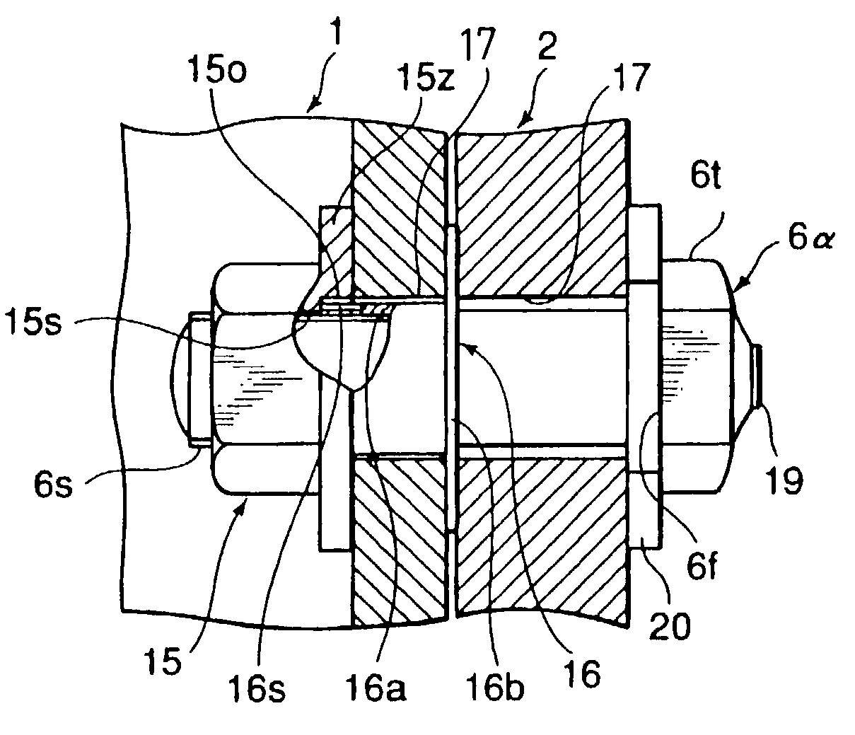
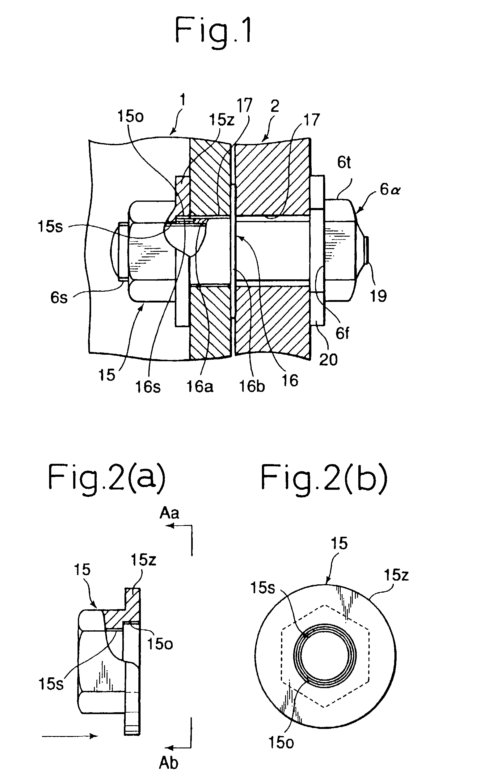
[0120]FIG. 1 shows the state of completion of the join by a Torque-Shear type high strength bolt 6α of the present invention in an example of the high strength bolted structure of a box section column 1 and split T-section 2 according to the present invention.

[0121]Note that a pair of an upper and lower split T-section 2 is used for one H-section beam when attaching an H-section beam to a box section column...

second embodiment

[0144

[0145]Next, a second embodiment of the present invention will be explained in detail with reference to FIG. 9 to FIG. 13(c). The second embodiment differs from the first embodiment in the method (structure) of securing the nut 15. A detailed explanation of the portions common with the first embodiment will be omitted.

[0146]FIG. 9 shows the state of completion of a join by a Torque-Shear type high strength bolt 6α in an example of a high strength bolted structure between a box section column and split T-section 2 according to the present invention. In FIG. 9, reference numeral 15 is a nut having a female thread 15s secured to the inner side of the box section column 1. As shown in FIG. 10(a) and FIG. 10(b), here it is of a shape formed integrally with the washer-like part 15z and secures the sleeve 25 to the washer-like part 15z.

[0147]This sleeve 25 is made of metal. It is secured by inserting and bonding its base end to a hole in the washer-like part 15z. Therefore, it has an ...

third embodiment

[0162

[0163]Next, a third embodiment of the present invention will be explained in detail with reference to FIG. 14 to FIG. 17(c). The third embodiment differs from the first and second embodiments in the method (structure) of securing the nut 15. Detailed explanations of portions common with the first and second embodiments will be omitted.

[0164]FIG. 14 shows the state of completion of the join by a Torque-Shear type high strength bolt 6α in an example of a bolted structure of a box section column 1 and a split T-section 2 according to the present invention. In FIG. 14, reference numeral 15 is a nut having a female thread 15s secured by bonding to the inner side of the box section column 1. As shown in FIG. 15(a) and FIG. 15(b), it is shaped formed integrally with a washer-like part 15z and is bonded and secured to the inner side of the box section column 1 by an adhesive b.

[0165]The Torque-Shear type high strength bolt 6α has a washer 20 inserted over it and is similar to the one o...


PUM


Abstract

A join structure comprises a box section column and spit T-section joined by a high strength bolt and a method secures a nut to an inside of the box section column. A Torque-Shear type high strength bolt is tightly tightened by a controlled tension and a joining method of a steel member uses that bolt. The join structure is comprised of a box section column, a split T-section attached to its outer surface, and a high strength bolt inserted from the outside of the split T-section and fastened with the nut. The nut is secured to the box section column by joining a sleeve secured to a washer formed integrally with the nut and a sleeve of a nut holding part from the outside of the column. The Torque-Shear type high strength bolt has a pintail for controlling the torque at its top.

Description

TECHNICAL FIELD[0001]The present invention relates to a high strength bolted structure and method of securing a nut, and to a Torque-Shear type high strength bolt and joining method using this bolt, as used in a bolted structure between a box section column and an H-section beam when constructing a steel structure building using rectangular steel tubes or box section members having rectangular sections or circular sections such as steel tubes as the columns and attaching the H-section beams (rolled members or welded members) to the box section columns through split T-sections, end plates, angles, fish plates, or other joining hardware.BACKGROUND ART[0002]In recent years, much use has been made of bidirectional “Rahmen” frame structures using rectangular steel tubes having hollow rectangular cross-sections (including those obtained by welding together plates or shapes) and other rectangular box section members and H-section steel (including those obtained by welding together plates o...

Claims


Application Information

Patent Timeline
IPC IPC(8): F16B21/00F16B31/00F16B31/02F16B37/04F16B37/06
CPCF16B31/021F16B37/04F16B37/06F16B37/064F16B37/041F16B37/062
Inventor UNO, NOBUYOSHINAGATA, MASAHIROTAMASAKI, HIDETOSHIKANAZAWA, SEIICHIHATANAKA, KIYOSHIMIYAGAWA, TOSHIO
Owner NIPPON STEEL CORP
Features
  • R&D
  • Intellectual Property
  • Life Sciences
  • Materials
  • Tech Scout
  • Unparalleled Data Quality
  • Higher Quality Content
  • 60% Fewer Hallucinations
Learn More