Method of controlling a wind power installation

Inactive Publication Date: 2007-04-17
WOBBEN ALOYS
View PDF15 Cites 20 Cited by
  • Summary
  • Abstract
  • Description
  • Claims
  • Application Information

AI Technical Summary

Benefits of technology

[0011]In a preferred development of the invention the twisting of cables which extend in particular from the machine housing into the pylon, or vice-versa, is taken into account when establishing the direction of movement for adjustment of the azimuth position of the machine housing. In that way avoidable damage can actually be avoided. The first predetermined wind speed of the order of magnitude of about 20 m/s is also usually referred to as the shut-down speed or limit speed. At that speed or a value somewhat thereabove, for example 25 m/s wind speed, most wind power installations shut down, that is to say, t

Problems solved by technology

A disadvantage with those known methods however is that no measures are specified for wind speeds which continue to rise, above the first predetermined wind speed, so that it is only possible to trust that the

Method used


Image

  • Method of controlling a wind power installation
  • Method of controlling a wind power installation
  • Method of controlling a wind power installation

Examples


Example

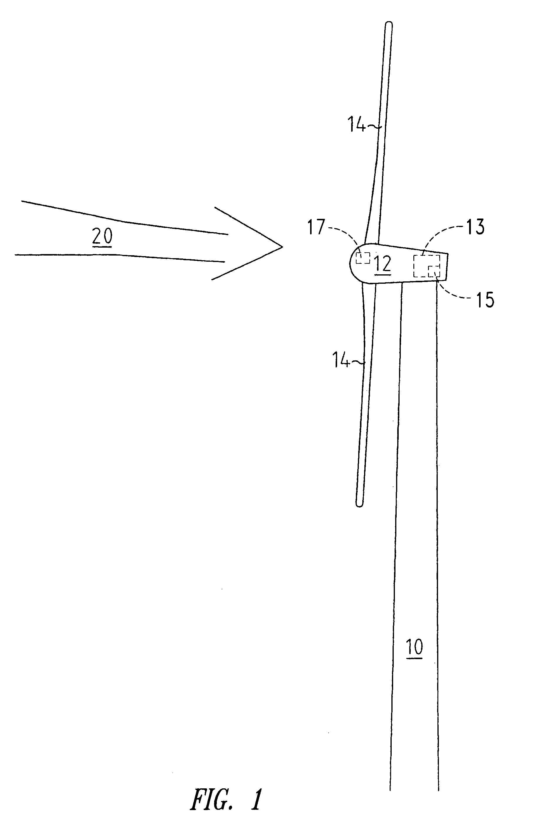
[0018]FIG. 1 shows a wind power installation which is in the form of a windward rotor—that is to say the rotor is at the side of the pylon 10, which is towards the wind. Disposed at the tip of the pylon 10 is the machine housing 12 with the generator (not shown) and the rotor blades 14.

[0019]In this Figure this wind power installation shown by way of example is illustrated in normal operation and the rotor blades 14 are so adjusted that they take the maximum power from the wind which is indicated by an arrow 20 to convert it into electrical energy.

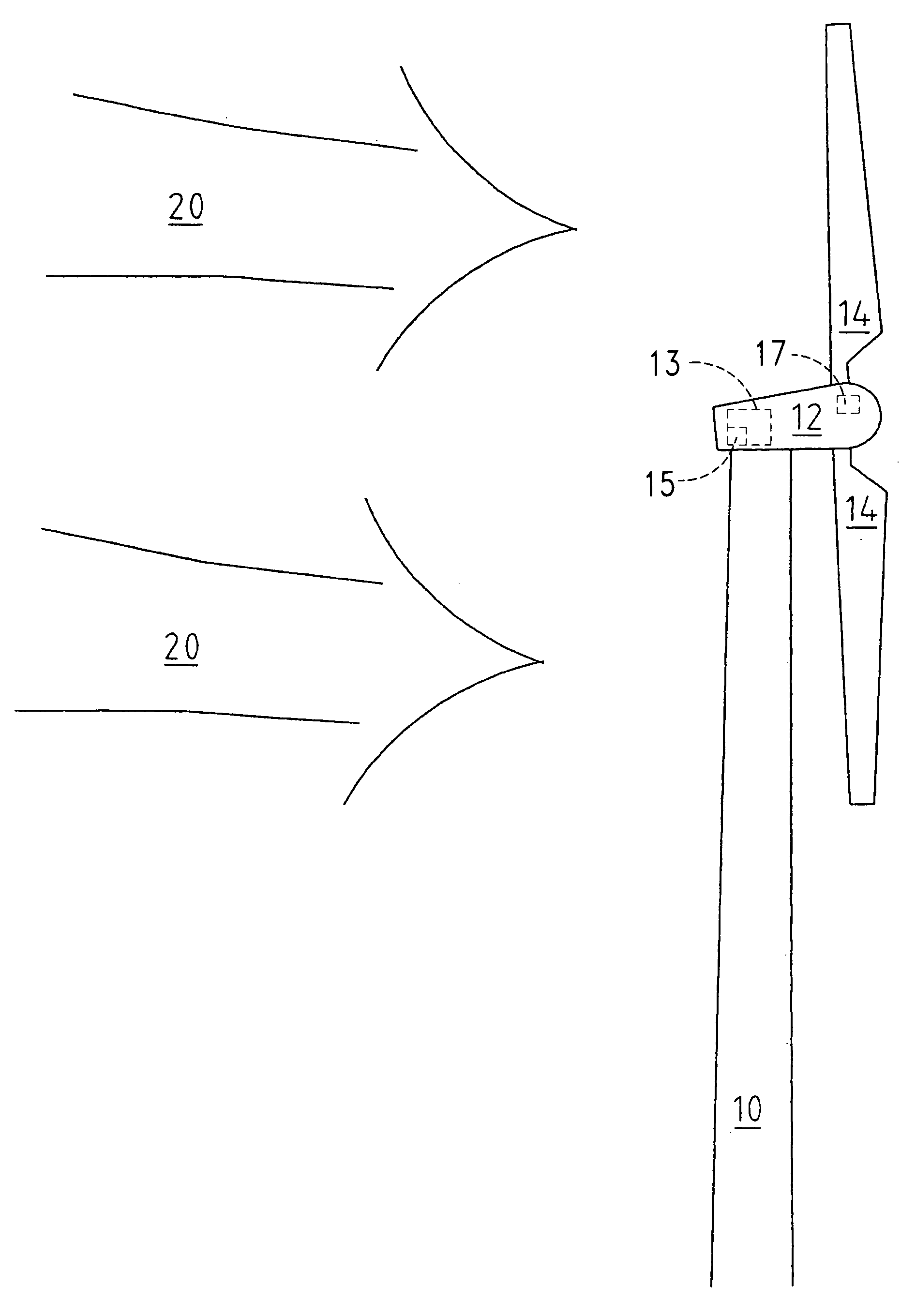
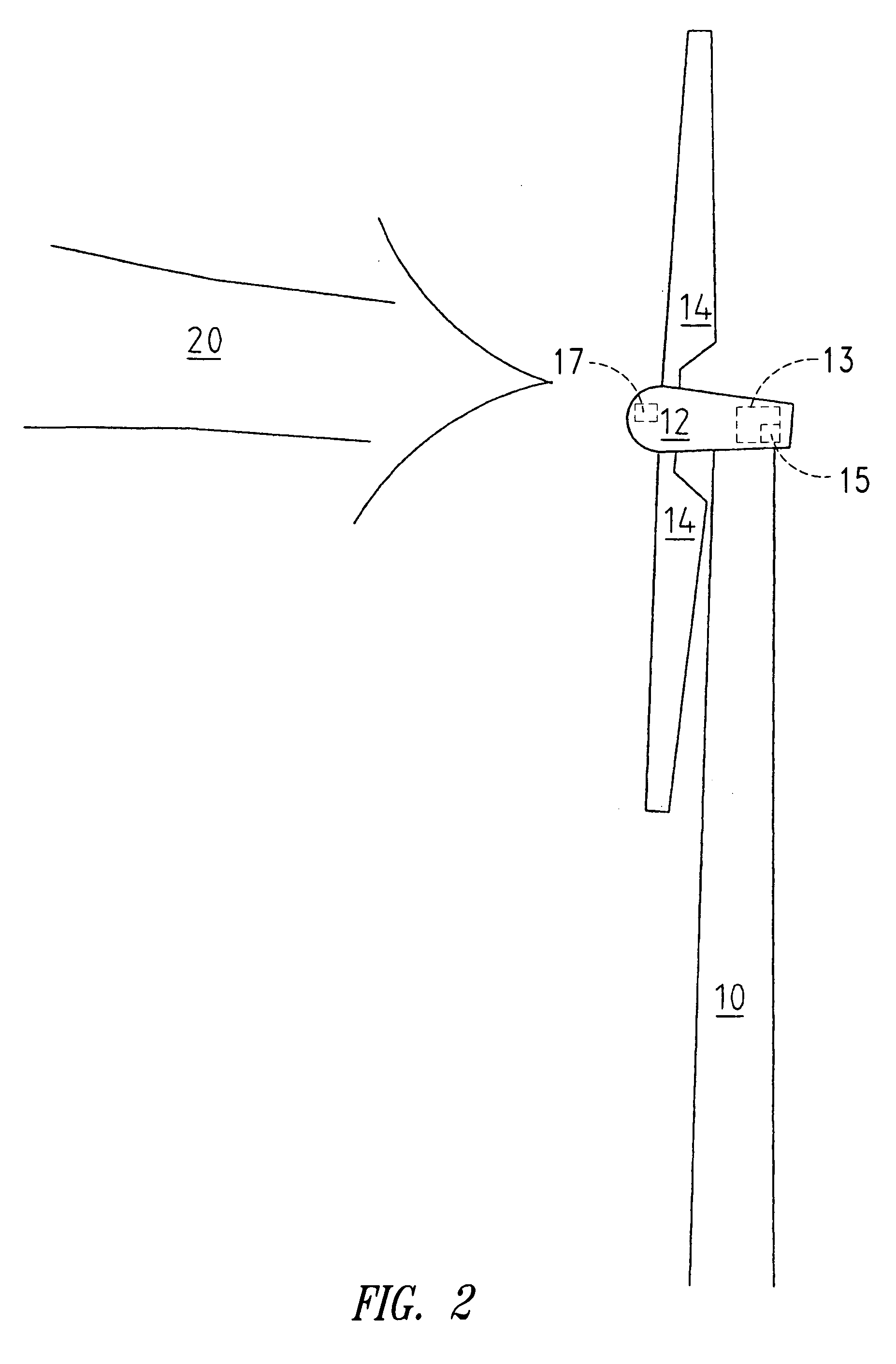
[0020]FIG. 2 also shows a wind power installation with a pylon 10, at the tip of which there is a machine housing 12. This Figure shows a possible setting of the rotor blades 14 which is brought about by the control 13 in accordance with the invention when a first predetermined wind speed, for example 20 m / s, is reached or exceeded. The control 13 may include at least one microprocessor 15. The wind loads on the rotor blades 14 are detecte...


PUM


Abstract

A method for controlling a wind power installation at very high wind speeds, in which there is predetermined a first wind speed at which the rotor blades of the wind power installation are put into a first predetermined setting. In addition, the method includes controlling the wind power installation during an extreme wind situation where the rotor blades moved to a position to reduce, as far as possible, mechanical loadings on the wind power installation caused by the extreme wind situation.

Description

TECHNICAL FIELD[0001]The present invention concerns a method of controlling a wind power installation at very high wind speeds, in which there is predetermined a first wind speed at which the rotor blades of the wind power installation are put into a first predetermined setting. The present invention further concerns a wind power installation, in particular for carrying out such a control method, comprising an azimuth drive and a rotor with at least one individually adjustable rotor blade.BACKGROUND OF THE INVENTION[0002]One method of controlling a wind power installation is described in DE 195 32 409. Another method of controlling a wind power installation at high wind speeds is described in Erich Hau, ‘Windkraftanlagen’ [‘Wind power installations’], Springer Verlag, 2nd edition, 1996, pages 89 ff and 235 ff.[0003]That known state of the art predominantly describes measures which are adopted to protect wind power installations from overloading, at very high wind speeds. In that res...

Claims


Application Information

Patent Timeline
IPC IPC(8): F03D7/04F03D7/02F03D11/00F03D11/04
CPCF03D7/0212F03D7/0268F03D7/042F05B2240/14Y02E10/723F05B2270/107F05B2270/32F05B2270/3201F05B2270/331F05B2270/1011Y02E10/72F03D7/04
Inventor WOBBEN, ALOYS
Owner WOBBEN ALOYS
Why Eureka
Try Eureka