Surface heating, method for its production, and heatable object, and seat occupancy recognition, seat with it, and seat occupancy recognition method

a surface heating and heatable object technology, applied in the direction of pedestrian/occupant safety arrangement, instruments, tractors, etc., can solve the problems of not only the expensive structure of a correspondingly equipped seat, but also the damage of upholstery layers and/or heating wires, and the inability to achieve optimal heat distribution over the surfa

Inactive Publication Date: 2007-04-17
BRAINSTOCK COM
View PDF9 Cites 19 Cited by
  • Summary
  • Abstract
  • Description
  • Claims
  • Application Information

AI Technical Summary

Benefits of technology

[0013]Especially for seating or lying substrates, useful surface heatings with electrically conducting plastics have not become known. However, simple, low-cost, and safely operated heatings would be desired for, for example, motor vehicle seats or mattresses.
[0016]As additional advantages, the invention makes possible a good, simple, and safely operated design and a good heat distribution.

Problems solved by technology

This requires not only an expensive structure of a correspondingly equipped seat, but rather has disadvantages, in particular in operation.
Thus, as a result of the stronger heating of surrounding layers in the immediate vicinity of the heating wires, there is a danger of overheating, which can lead to damage to the upholstery layers and / or the heating wires and can even cause a fire.
Furthermore, the heat distribution over the surface is not optimal, since in the area of the heating wires, the temperature is always higher than at a distance from it.
Another disadvantage with this known mode of construction is the mechanical stress which the heating wires are exposed to, if a passenger uses the seat, since in this way, the conductor wires can break, which can lead to a function failure and / or results in another possible fire source.
Use of a film made of electrically conducting plastics on the carrier structure of a motor vehicle seat, however, is not possible, since then all of the upholstery layers etc., lying over it, would be heated, until the heat came to a sitting passenger, which would consume a very large amount of energy.

Method used


Image

  • Surface heating, method for its production, and heatable object, and seat occupancy recognition, seat with it, and seat occupancy recognition method
  • Surface heating, method for its production, and heatable object, and seat occupancy recognition, seat with it, and seat occupancy recognition method
  • Surface heating, method for its production, and heatable object, and seat occupancy recognition, seat with it, and seat occupancy recognition method

Examples


Embodiment Construction

[0042]In the description of the invention below, with the aid of embodiment examples, the same reference symbols are used throughout for the same or similarly acting parts. Even if not all details of the graphic depictions are treated in the following description, individual features and their relationships can be readily deduced by a specialist—if they are depicted in the figures—from the figures themselves.

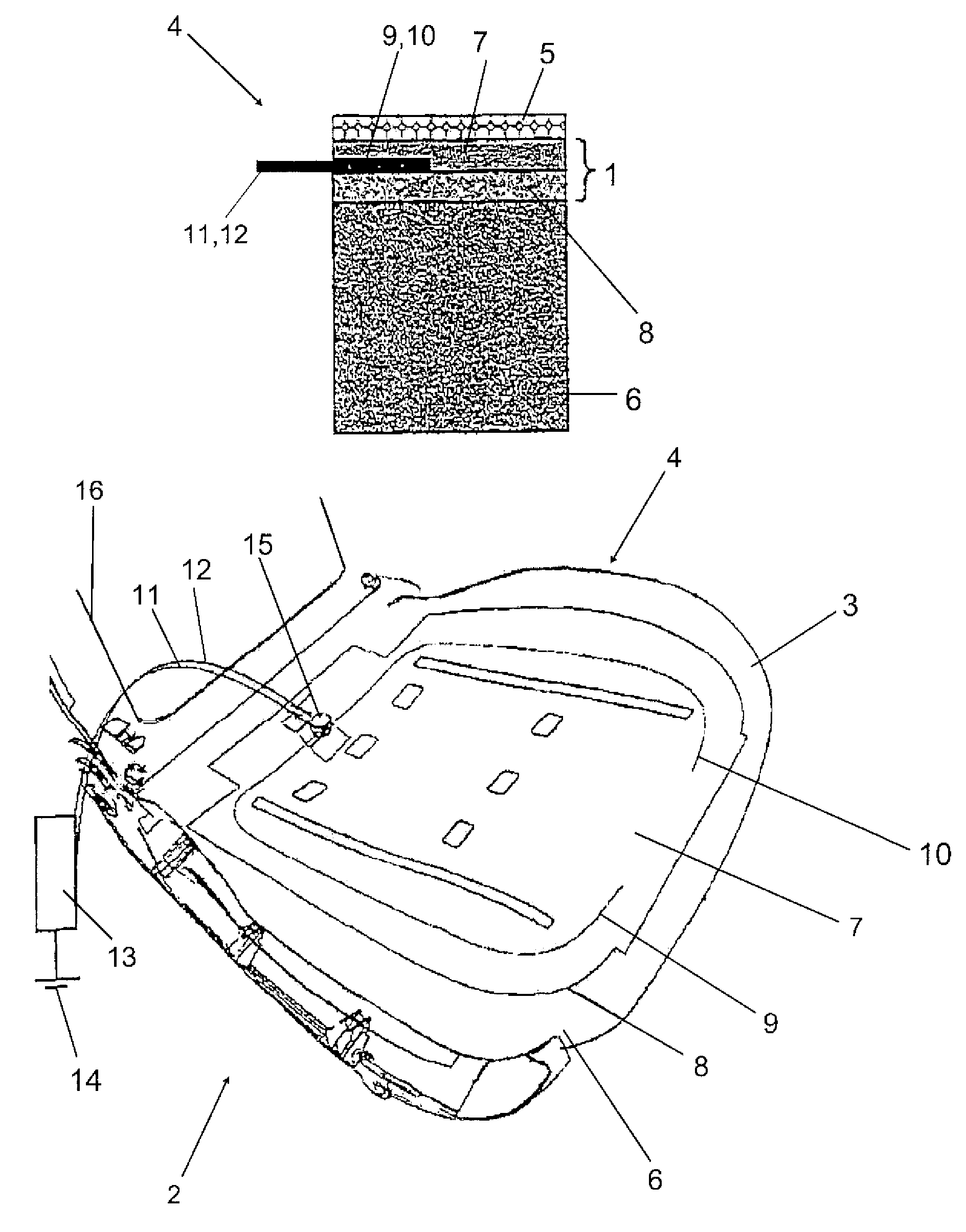
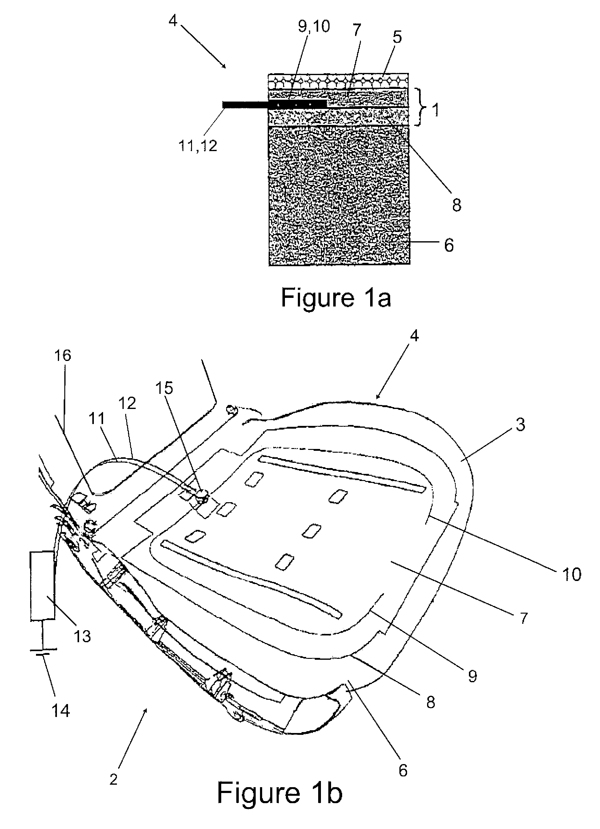
[0043]A motor vehicle seat 2, in whose seat surface part 3, a seat heating 4 is integrated, is shown, as a first embodiment example of a surface heating 1, in FIGS. 1a and 1b, in a cut or perspective schematic drawing.

[0044]The structure of the seat surface part 3 in the surroundings of the surface heating 1 is shown in FIG. 1a, in which a cross-sectional cut is depicted through the corresponding layers / components of the seat surface part 3. The surface of the seat surface part 3 is formed by a seat cover 5, which can be made of fabric, synthetic leather, or leather or other sui...


PUM


Abstract

A system for recognizing the occupancy of a seat, containing elements made of electrically conducting synthetic material, especially strips made of electrically conductive polyurethane. A seat equipped with the system. A method for recognizing seat occupancy whereby an alteration in resistance of the electrically conductive material occurring in a change of weight is detected.

Description

RELATED APPLICATION[0001]This application is a continuation of International Application No. PCT / DE02 / 02456, filed Jul. 4, 2002, the contents of which are here incorporated herein in their entirety.BACKGROUND OF THE INVENTION[0002]1. Field of the Invention[0003]The invention relates to surface heating, method for its production, and heatable object, and seat occupancy recognition, seat with it, and seat occupancy recognition method, and a heatable object with such a surface heating and a method for the production of a surface heating. More particularly, the invention under consideration relates to a seat heating, a heated seat, and a method for its production. Preferably, the invention also relates to a heating for side linings and floor coverings, particularly in vehicles, side linings and floor coverings equipped with it, particularly in vehicles, and a method for its production. Furthermore, the invention under consideration relates to a mattress heating, a heated mattress, and a...

Claims


Application Information

Patent Timeline
Patent Type & Authority Patents(United States)
IPC IPC(8): H05B1/00H05B11/00H05B3/00B60N2/56H05B3/34
CPCB60N2/5685H05B3/34H05B2203/013H05B2203/017H05B2203/029
Inventor DIEMER, MICHAELDIEMER, STEFAN
Owner BRAINSTOCK COM
Why Eureka
Try Eureka