High speed rotor

a rotor and high-speed technology, applied in the field of permanent magnet electromechanical machines, can solve the problems of rare earth magnets typically having poor mechanical properties, fewer permanent magnet electric motors or generators that are rated over several hundred kilowatts (kw), and providing high-speed shaft rotation, so as to prevent radial movement of magnets.

Inactive Publication Date: 2007-04-17
DRS POWER & CONTROL TECH
View PDF6 Cites 28 Cited by
  • Summary
  • Abstract
  • Description
  • Claims
  • Application Information

AI Technical Summary

Benefits of technology

[0005]Surface mounted permanent magnet rotors are conceptually simple, and therefore, perceived to be less costly. Typically, the magnets are retained on the outer diameter of the rotor in one of four ways. First, the magnets may be enclosed in a non-ferromagnetic holder that is attached to the rotor by mechanical means such as fasteners, a version of “tongue and groove” geometry, or a combination of both. Second, the magnets may be glued directly to the outer surface of the rotor. Third, the magnets may be glued directly to the outer surface of the rotor, and thereafter, a non-ferromagnetic, metal sleeve is shrink-wrapped around the magnets. Fourth, the magnets may be glued directly to the outer surface of the rotor, and thereafter, the rotor assembly is wrapped with a high strength, high modulus composite fiber / epoxy.
[0042]As best seen in FIGS. 1 and 2, rotor assembly 18 is constructed by axially sliding ring assemblies 48 onto rotor 38 such that lobes 42 of rotor 38 extend through a corresponding lobe-shaped cutouts 76 in magnet retention ring 50 and gaps 86 defined by laminated pole pieces 70 of corresponding stacks 80 of ring assemblies 48. Retaining bars 74 projecting from end surfaces 72 of magnet retention elements 56 are seated within corresponding retaining bar receipt cavities 54 in second sides 50b of magnet retention ring 50 of adjacent ring assemblies 48a, FIGS. 2 and 5, as heretofore described, in order to interlock adjacent ring assemblies 48. Magnets 52a–52d are slid axially along corresponding lands 40a–40d of outer surface 40 of rotor 38 such that magnets 52a–52d extend through corresponding magnet cutouts 78 in ring assemblies 48 and such that magnets 52a–52d are disposed between corresponding pairs of stacks 80 of laminated pole pieces 70 in ring assemblies 48. It is contemplated to provide shims 92 between magnets 52a–52b and radially inner surfaces 58 of corresponding magnet retention elements 56 of each ring assembly 48 so as to prevent radial movement of magnets 52a–52d during the rotation of rotor assembly 18, and thermal growth of the rotor 18 as the machine warms during operation.

Problems solved by technology

Presently, however, there are very few permanent magnet electric motors or generators that are rated over several hundred kilowatts (kW) and that provide high speed shaft rotation.
While shaft speeds of up to approximately 100,000 revolutions per minute (rpm) have been achieved in permanent magnet electric motors and generators having low power ratings, higher rated machines are typically limited to shaft speeds of several thousand rpms or less.
As is known, rare earth magnets typically have poorer mechanical properties than the other elements of the rotor, and as such, cannot be used as load bearing elements in the rotor design.
At very high frequencies, such as those experienced in machines running significantly faster than approximately 3600 rpms, the heating of the metallic sleeve can damage the magnets.
Alternatively, simply gluing the magnets to the rotor is not feasible for high speed applications as the mechanical properties of the magnets are not up to the task of holding together when subjected to the tensile loads that results from high rotational speeds.
Further, finding a suitable adhesive for gluing the magnets on the rotor may be difficult.
An additional drawback to surface mounted permanent magnet rotors is the cost of the magnets.
These manufacturing steps can add significantly to the overall cost of the final product.
Finally, surface mounted rotors are more susceptible to damaging the magnets in “off-design” operating conditions, such as pole slips or stator short circuits.
However, the mechanical properties of the magnet materials and pole pieces limit the surface speeds such machines can achieve, making them most suitable for low RPM, high torque / power design.

Method used


Image

  • High speed rotor
  • High speed rotor
  • High speed rotor

Examples


Embodiment Construction

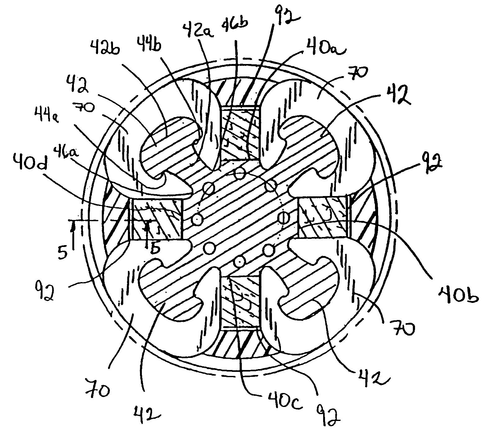
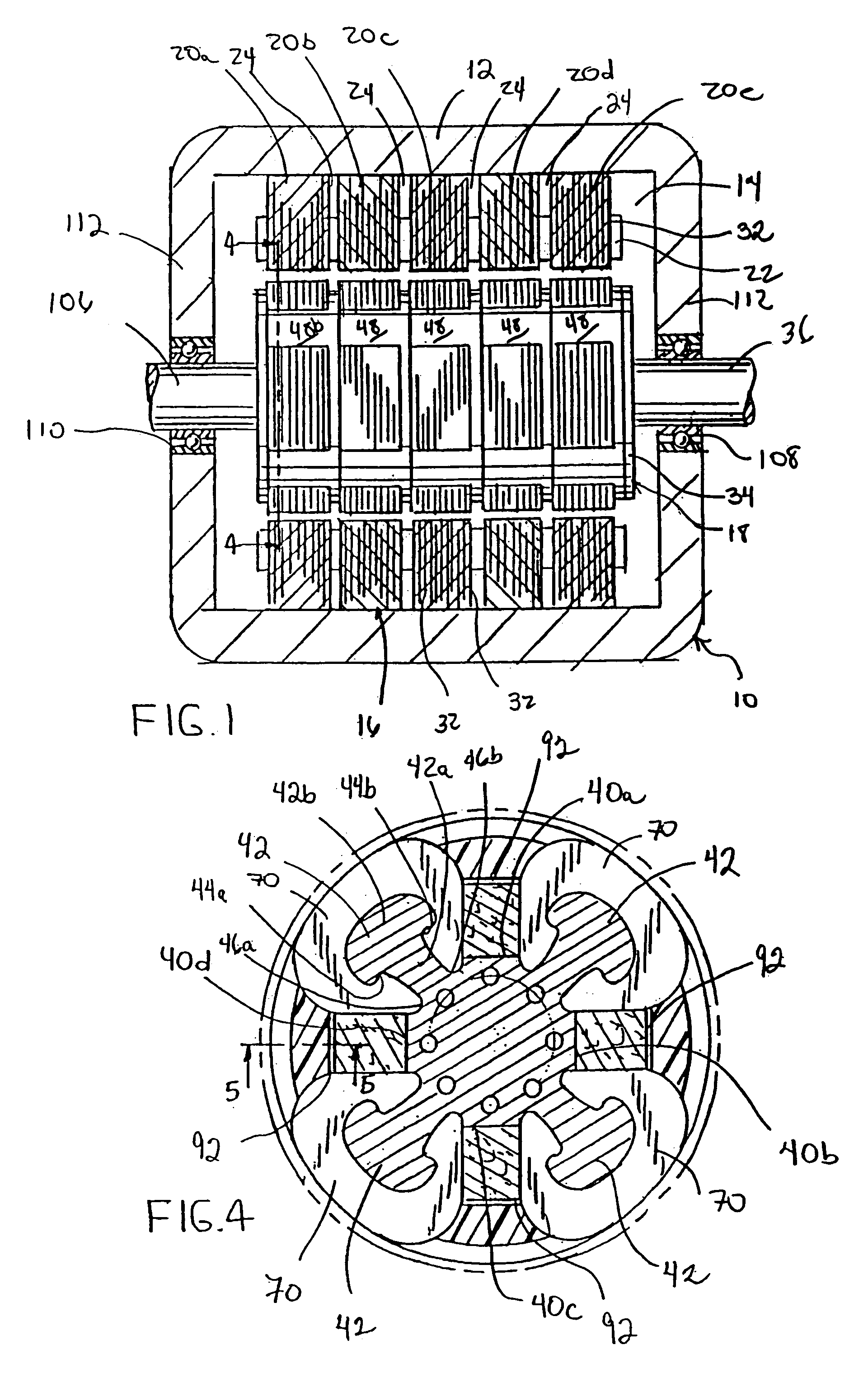
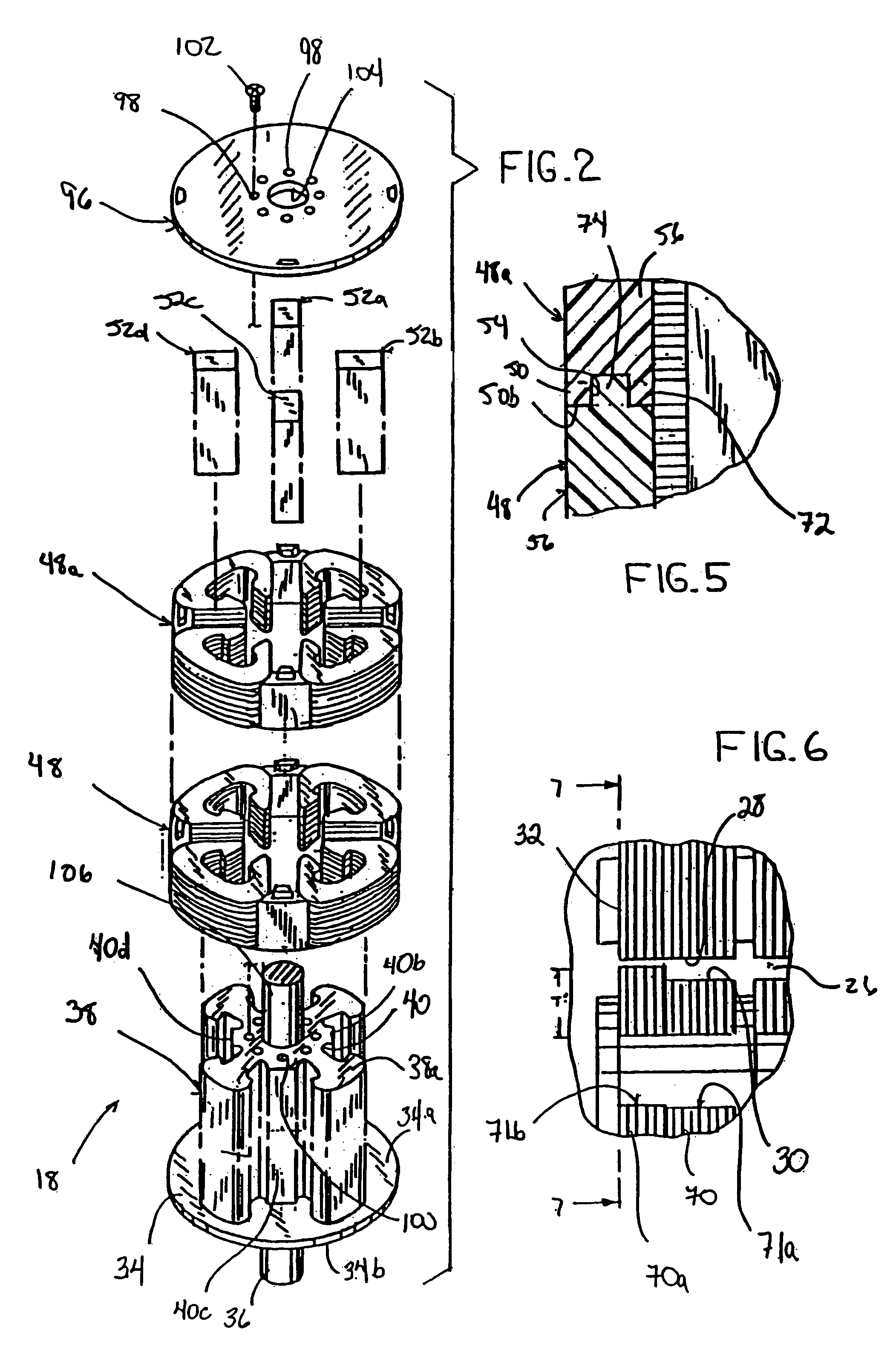
[0033]Referring to FIG. 1, an electromechanical machine incorporating a rotor assembly 15 in accordance with the present invention is generally designated by the reference numeral 10. Electromechanical machine 10 includes an enclosure 12 which defines an interior 14 for receiving stator 16 and rotor assembly 18, as hereinafter described. Stator 16 includes a plurality of stator stacks 20a–20e which are positioned adjacent each other and supported by stator frame 22. Radial cooling channels 24 extend between corresponding pairs of stator stacks 20a–20e so as to allow air or an alternate coolant to pass therethrough into air gap 26 defined between the radially inner surfaces 28 of stator stacks 20a–20e and radially outer surface 30 of rotor assembly 18, FIG. 6. As best seen in FIGS. 1 and 6, stator stacks 20a–20e are formed by a plurality of stator pole pieces 32 laminated together.

[0034]Referring to FIGS. 2–3, rotor assembly 18 includes an end plate 34 having first and second opposit...


PUM

PropertyMeasurementUnit
speedaaaaaaaaaa
shaft speedsaaaaaaaaaa
mechanical propertiesaaaaaaaaaa

Abstract

An electromagnetic machine is provided. The machine includes a stator extending along a longitudinal axis and having an inner surface defining a rotor receipt cavity. The rotor extends along and is rotatable about the longitudinal axis within the rotor receipt cavity. A plurality of ring assemblies are supported on the rotor and a plurality of magnets are circumferentially spaced about the rotor and extend through the ring assembly. Each magnet is generally parallel to the axis of the rotor.

Description

[0001]The present application is a continuation application of U.S. patent application Ser. No. 10 / 408,331 filed Apr. 7, 2003, now U.S. Pat. No. 6,750,584 which is a divisional application of U.S. patent application Ser. No. 09 / 063,362 filed Apr. 21, 1998, now U.S. Pat. No. 6,750,584, which issued on Jun. 15, 2004 the disclosure of which is incorporated herein by reference.FIELD OF THE INVENTION[0002]This invention relates to electromechanical machines, and in particular, to a permanent magnet electromechanical machine incorporating a high speed rotor design.BACKGROUND AND SUMMARY OF THE INVENTION[0003]In order to meet the constant demand for efficient, power dense drivers for industrial and commercial applications, high speed, permanent magnet electric motors and generators are required. Presently, however, there are very few permanent magnet electric motors or generators that are rated over several hundred kilowatts (kW) and that provide high speed shaft rotation. While shaft spee...

Claims


Application Information

Patent Timeline
Patent Type & Authority Patents(United States)
IPC IPC(8): H02K1/18G01N29/04G01N29/11G01N29/46
CPCG01N29/041G01N29/11G01N29/46G01N2291/102G01N2291/2634
Inventor SMITH, JAMES S
Owner DRS POWER & CONTROL TECH
Why Eureka
Try Eureka