Emulation of long delay chain by ring oscillator with floating body-tied body devices

a delay chain and ring oscillator technology, applied in pulse manipulation, instruments, pulse technique, etc., can solve the problems of reducing the number of stages, requiring thousands of delay chains, and expensive measuring processes, so as to reduce the number of stages and accurately measure the first and second switching speeds

Inactive Publication Date: 2007-04-17
GLOBALFOUNDRIES INC
View PDF4 Cites 8 Cited by
  • Summary
  • Abstract
  • Description
  • Claims
  • Application Information

AI Technical Summary

Benefits of technology

[0011]A method and apparatus for reducing the number of stages for measuring first and second switching speeds for PD / SOI transistors uses an inverter circuit which includes: a p-channel body-tied transistor; an n-channel body-tied transistor, coupled at their drains and gates; and a first and a second group of components tied to the bodies of the transistors. The first group restores body potentials for the transistors if the inverter circuit belongs to an even numbered stage of a ring oscillator. The second group provides body potentials for the transistors if the inverter circuit belongs to an odd numbered stage. After each transition of a waveform, the body potentials for the PD / SOI transistors are restored to the original potentials as stored in the capacitors. In this manner, a ring oscillator with a fewer number of stages may be used to accurately measure the first and second switching speeds.

Problems solved by technology

However, with a ring oscillator, the first and second switching speeds are not measurable, as the ring oscillator runs in steady state.
However, in order to accurately measure the difference between the first and second switching speeds, the delay chain usually requires thousands of stages.
This utilizes a lot of area on a silicon wafer, making the measuring process costly.

Method used


Image

  • Emulation of long delay chain by ring oscillator with floating body-tied body devices
  • Emulation of long delay chain by ring oscillator with floating body-tied body devices
  • Emulation of long delay chain by ring oscillator with floating body-tied body devices

Examples


Embodiment Construction

[0021]The present invention provides a method and apparatus for reducing a number of stages for measuring first and second switching speeds for PD / SOI transistors. The following description is presented to enable one of ordinary skill in the art to make and use the invention and is provided in the context of a patent application and its requirements. Various modifications to the preferred embodiment will be readily apparent to those skilled in the art and the generic principles herein may be applied to other embodiments. Thus, the present invention is not intended to be limited to the embodiment shown but is to be accorded the widest scope consistent with the principles and features described herein.

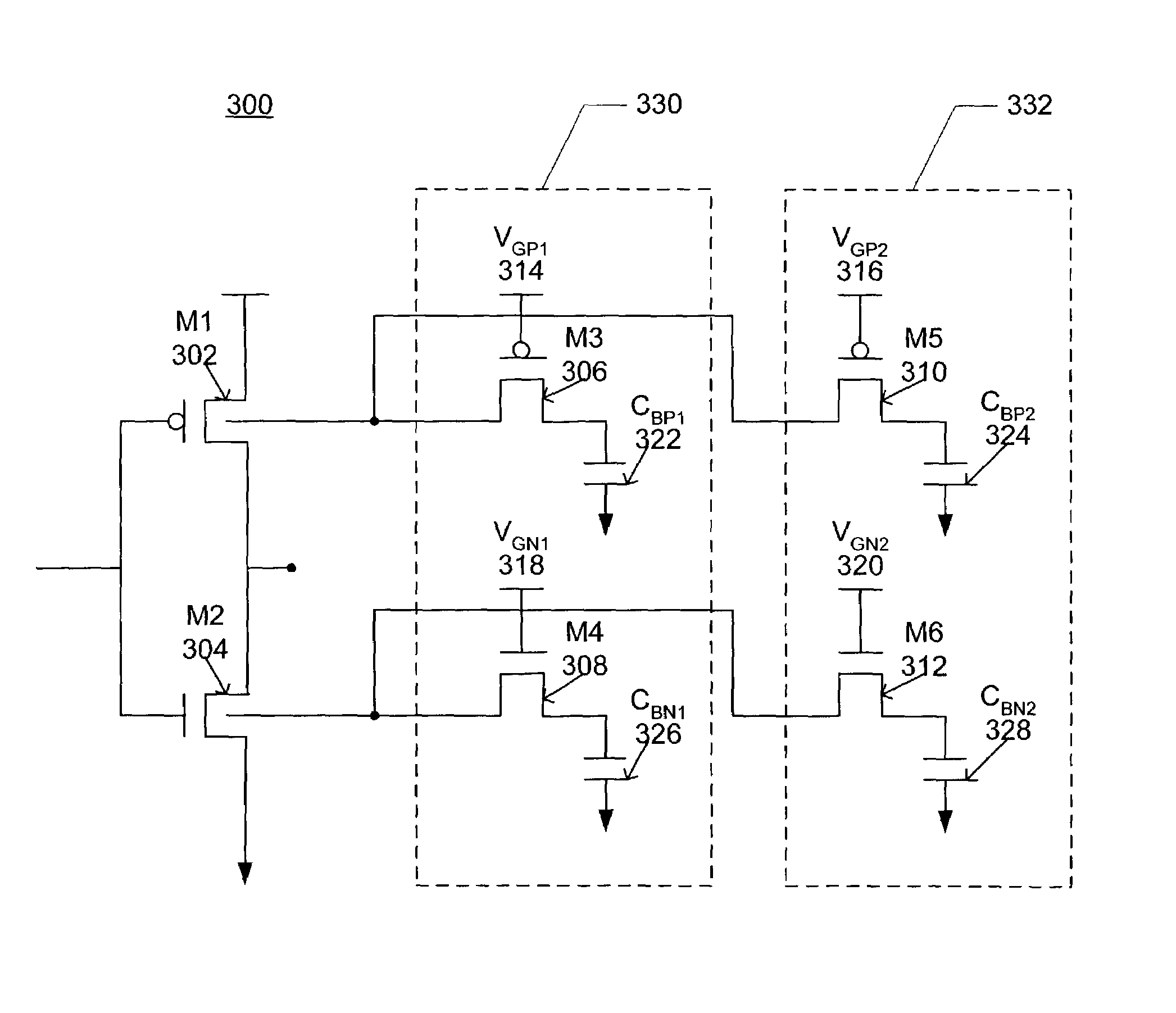
[0022]In the method and apparatus in accordance with the present invention, an inverter circuit comprising PD / SOI body-tied transistors are used in each stage of a ring oscillator. The original body potentials for the transistors are stored in capacitors. After each transition of a wavef...


PUM


Abstract

A method and apparatus for reducing the number of stages for measuring first and second switching speeds for PD / SOI transistors uses an inverter circuit which includes: a p-channel body-tied transistor; an n-channel body-tied transistor, coupled at their drains and gates; and a first and a second group of components tied to the bodies of the transistors. The first group restores body potentials for the transistors if the inverter circuit belongs to an even numbered stage of a ring oscillator. The second group provides body potentials for the transistors if the inverter circuit belongs to an odd numbered stage. After each transition of a waveform, the body potentials for the PD / SOI transistors are restored to the original potentials as stored in the capacitors. In this manner, a much smaller ring oscillator with fewer number of stages may be used to accurately measure the first and second switching speeds.

Description

FIELD OF THE INVENTION[0001]The present invention relates to delays in floating body SOI devices, and more particularly to the use of ring oscillators in measuring these delays.BACKGROUND OF THE INVENTION[0002]The use of partially depleted / silicon-on-insulator (PD / SOI) transistors is known in the industry. FIG. 1 illustrates a cross-sectional view of a PD / SOI transistor. The elements of the transistor 100 are not shown in proportion. The transistor 100 comprises a substrate 114. Formed on the substrate are a source 102, a drain 104, and a floating body region 110 between the source 102 and drain 104. Above the source 102, drain 104, and body region 110 are a gate 106 and insulator layers 108. The insulator layers 108 can be oxide, nitride, a combination of oxide and nitride, or some other insulating material. Another insulator layer 112 resides between the floating body 110 and the rest of the substrate 114, isolating the body 110. When the transistor 100 is charged after being dorm...

Claims


Application Information

Patent Timeline
Patent Type & Authority Patents(United States)
IPC IPC(8): G05F1/10H01L29/786H03K5/00H03K19/00
CPCH01L29/78615H03K19/0027H03K2217/0018H03K2005/00071
Inventor KLEIN, RICHARD K.PELELLA, MARIO M.
Owner GLOBALFOUNDRIES INC
Why Eureka
Try Eureka