RF accelerator for imaging applications

a technology of accelerators and electron beams, applied in the direction of discharge tubes/lamp details, x-ray tubes, nuclear engineering, etc., can solve the problems of limiting the operation of tubes, limiting the design aspects of x-ray apparatuses, and high voltage insulators being typically bulky and expensive, so as to improve reliability and reduce the cost of components

Active Publication Date: 2007-04-17
GE MEDICAL SYST GLOBAL TECH CO LLC
View PDF22 Cites 63 Cited by
  • Summary
  • Abstract
  • Description
  • Claims
  • Application Information

AI Technical Summary

Benefits of technology

[0012]The electrons accelerated by the cavity are used to generate x-rays by interacting with a solid or liquid target. The electron accelerator may be used in an arc source for a stationary computed tomography application, in an x-ray tube, as a booster for an electron gun, and other imaging applications. For example, the electron accelerator may be used to replace static high voltage means in traditional x-ray tubes. There is no need for a high voltage insulator, thereby eliminating the drawbacks associated therewith.
[0014]All cathode supplies and controls in an x-ray generating device using an RF cavity for acceleration are at ground potential. This enables better reliability and lower cost of the components.

Problems solved by technology

Such high voltage operation severely limits design aspects of the x-ray apparatus because it requires the high voltage to be insulated from other components of the x-ray tube.
High voltage insulators are typically bulky and expensive.
However, rapidly growing centripetal forces due to increased gantry speed severely limit the tube's operation.
The insulator must be large which poses problems of cost, space, weight, and reliability concerns.
A large insulator is very costly and very bulky adding considerable size and weight to the equipment.
For the higher electric fields more solid insulation is typically needed, thereby increasing the likelihood of failure under operation due to material defects.
Failures of solid insulation are either surface flashovers or electrical breakdown in the bulk of the material.
Another disadvantage of solid insulation is the need to provide cathode supplies and controls on a high-voltage level.
Generally feedthroughs increase the cost and complexity of the solid insulation and degrade the overall reliability of the solid insulation itself.
Additionally, active electronic controls that are operated at high voltage levels to provide bias voltages are specifically susceptible to being damaged as a consequence of transient high voltage events, also called spits.
Another disadvantage of using dc electric fields in x-ray tubes, especially for CT, is the need for dual energy applications, which are of particular clinical value in differentiating cancerous tissue and benign calcification.
Due to limitations caused by the typical capacitive and inductive load of state-of-the-art generators, x-ray tubes, and connecting cable assemblies, such a square high-voltage waveform at 6 kHz cannot be achieved.

Method used


Image

  • RF accelerator for imaging applications
  • RF accelerator for imaging applications
  • RF accelerator for imaging applications

Examples


Embodiment Construction

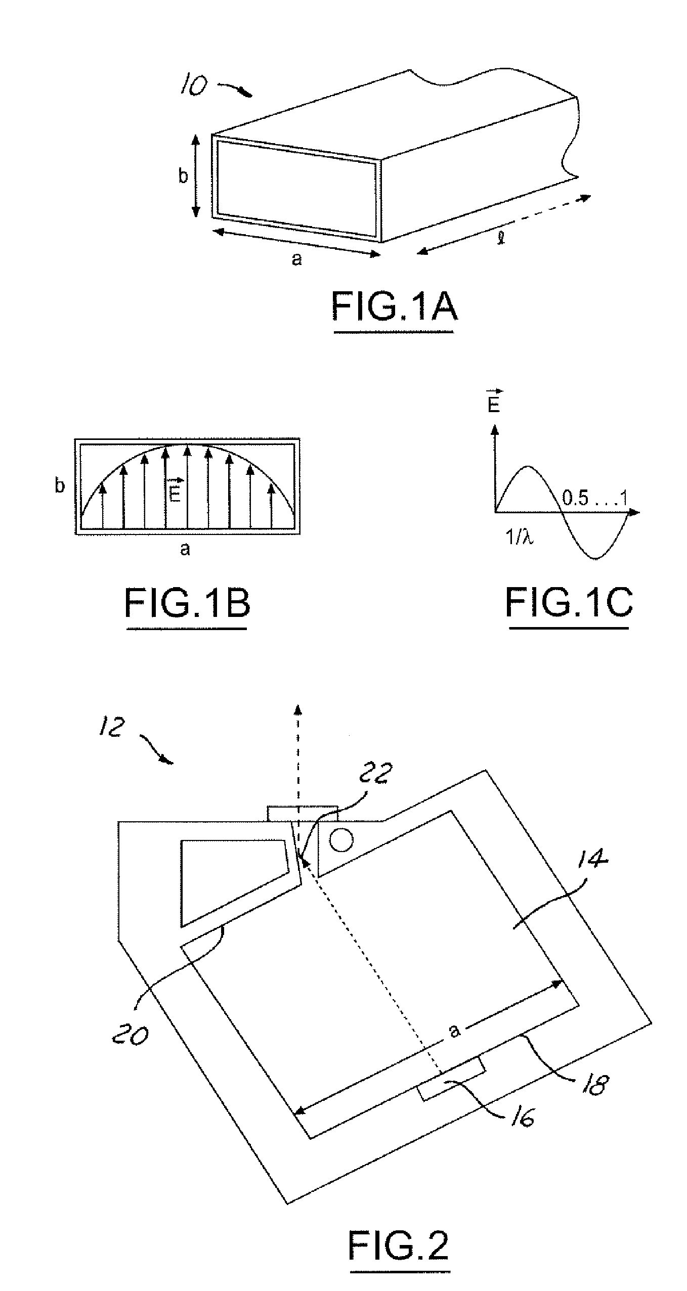
[0027]Referring to FIGS. 1A, 1B and 1C, there is shown an example of the electric field distribution for the TE10-mode in a rectangular waveguide. The waveguide cavity 10 has a width dimension, a; a height dimension, b; and a length, l as shown in FIG. 1A. FIG. 1B shows the electric field distribution E at a particular moment in time, in the cavity 10 for TE10-mode of the electromagnetic wave, E shown in FIG. 1C.

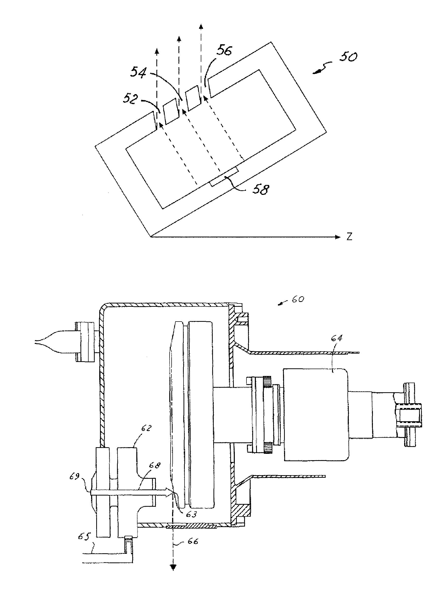
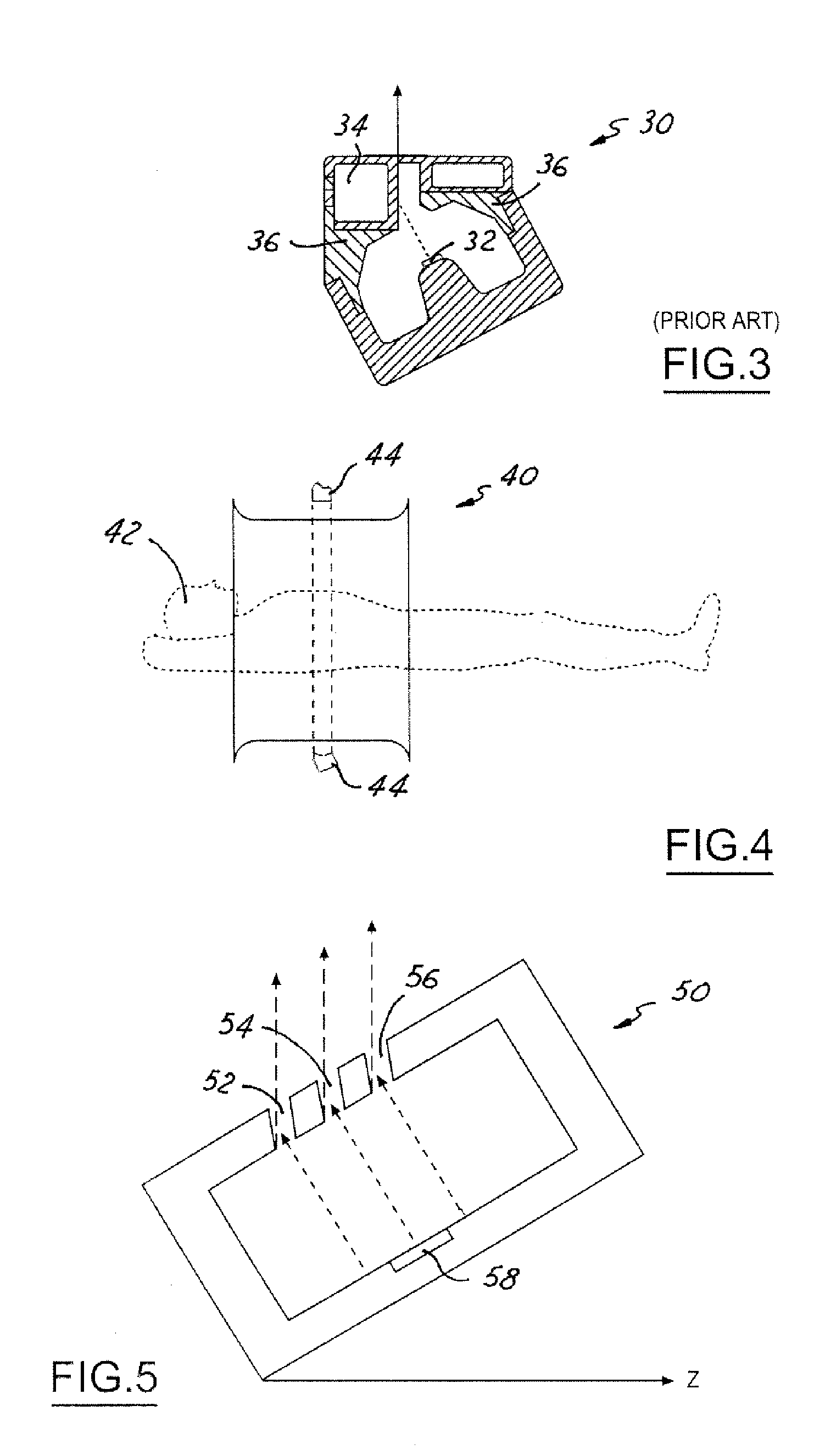
[0028]Referring now to FIG. 2, the accelerator is shown in cross section as a CT arc source 12 application. A rectangular wave-guide cavity 14 has an electron emitter 16 placed on the bottom face 18, which corresponds to the width dimension, a, of the rectangular waveguide. For an electric field distribution as shown in FIG. 1B, the electrons emitted from the source are accelerated across the guide, along the path corresponding to the height dimension, b, to the opposing, or upper face, 20 of the cavity 14. During the negative half wave of the electric field, as in FIG. 1C f...


PUM


Abstract

The present invention is an RF cavity for accelerating electrons in imaging applications such as x-ray tubes and CT applications. An RF cavity having electron emitters placed therein accelerates the electrons across the cavity. The geometric shape of the cavity determines the electromagnetic modes that are employed for the acceleration of electrons. The fast electrons are used to generate x-rays by interacting with a target, either a solid or a liquid target. The electron accelerator may be used in an arc source for a stationary computed tomography application, in an x-ray tube, as a booster for an electron gun, and other imaging applications.

Description

CROSS-REFERENCE TO RELATED APPLICATIONS[0001]This application claims priority to provisional patent application No. 06 / 524,987 filed on Nov. 25, 2003, now abandoned.TECHNICAL FIELD[0002]The present invention relates generally to a source for generating an electron beam and more particularly to a microwave driven electron beam for imaging applications such as stationary CT applications and x-ray tubes.BACKGROUND OF THE INVENTION[0003]Computerized tomographic (CT) scanners employ radiation from x-ray tubes. The radiation is focused on a target and the target is typically an arrangement of x-ray detectors that are positioned such that a tomographic image of one or more slices through a subject is reconstructed to produce an image.[0004]The x-ray tube assembly typically operates with high voltage fed by control leads that pass through the housing into the tube. During operation, electrons are emitted from a source, usually a heated filament within a cathode, and accelerated to a focal s...

Claims


Application Information

Patent Timeline
Patent Type & Authority Patents(United States)
IPC IPC(8): H01J35/02H05G2/00H01J3/02H01J35/06H05H7/18H05H15/00
CPCH01J3/021H01J35/06H05H7/18H05H15/00H01J35/065
Inventor LEMAITRE, SERGIO
Owner GE MEDICAL SYST GLOBAL TECH CO LLC
Why Eureka
Try Eureka