Siding panel tab and slot joint

a technology of siding panels and slots, applied in the field of panels, can solve the problems of horizontal abutments, require joints, overlap joints, etc., and achieve the effects of facilitating insertion, and reducing the incidence of partial joint engagemen

Active Publication Date: 2007-04-24
CERTAINTEED CORP
View PDF9 Cites 40 Cited by
  • Summary
  • Abstract
  • Description
  • Claims
  • Application Information

AI Technical Summary

Benefits of technology

[0026]According to another aspect, a discontinuous tab and slot arrangement is provided for at least the butt joints of siding panels. The engageable tabs and slots are provided with lead-in ramp edges that facilitate engagement and thereby reduce the incidence of partial joint engagement. Inasmuch as the joints are engageable without the need for endwise clearance, the longitudinal insertion depth can be large without a corresponding need for endwise clearance. Furthermore, the tabs and slots are arranged to engage frictionally, preferably both in the butt joints and in overlap joints, so that the installer can temporarily affix a next course to an installed course, the temporary position being held by the joints, permitting fine adjustments of spacing and joint gap.
[0029]Accordingly, the invention provides a panel, particularly for polypropylene and other similar siding materials, and also for applications similar to siding, mounted in lapped courses with butt joints at which panels attach in a direction of elongation. The opposite ends have complementary tabs, edges forming tabs and / or slots that fit together to joint the panels by a normal end-to-end approach of the abutting panels. According to an aspect of the invention, openings for the tabs also permit engagement by relative movement in a direction perpendicular to that normal direction. This reduces or eliminates the need for assembly space.
[0031]In the case of two or more tabs and / or gaps for a given length of panel, the tabs and the solid parts of the under-lap edge form fingers that can be interleaved. Interleaving the raised tabs through parts of the under-lap edge between the gaps allows the installer relatively to position the under-lap edges in line with the slots formed between the raised tabs and the backside surfaces of overlap edges. The motion is at least partly normal to the plane of the surface on which the siding is to be installed. After interleaving, the panels are relatively moved at least partly parallel to the surface and perpendicular to the direction of elongation of panels, thus placing portions of the under-lap edge between respective tabs and overlap edges on the backside of the panels. The joint is made without the need for endwise clearance in the direction of elongation of the panels.

Problems solved by technology

Nevertheless, horizontal abutments occur and require joints.
Both endwise joints and overlap joints present practical problems.
It also does not help or account for expansion and contraction in a direction perpendicular to the elongation of the course.
This presents a quandary in that if there is a span, the installer cannot use the vertical joints as a means to reference the position of the next overlapping course relative to an installed course.
These errors tend to become noticeable after the installation has been completed.
Expansion and contraction issues, for example, may cause binding and buckling from insufficient expansion clearance.
Even apart from thermal expansion, any particularly complex joint structures, such as butt joints that have two or more elements that need to be engaged simultaneously, may be discovered after installation to have been only partially engaged.
Overlapping is not practical in panel designs that have a thicker material such as injection molded polypropylene (also sometimes described as “vinyl” siding), which might typically be 0.080 to 0.150 inches thick.
Overlapping is also not practical when the siding has a depth or thickness feature such as deep simulated wood grain or ridging, or if the siding design comprises discrete laterally positioned elements, such as wooden shingles or cedar shakes, which can be even thicker.
One drawback is that the installer needs to assemble many such joints while also being appropriately concerned about all the other requirements such as placement of fasteners in slotted holes, correct alignment, position and vertical arrangement, etc.
Whether the butt jointed panels are relatively longer or shorter in the direction of elongation, there is still an issue as to expansion and contraction in a direction perpendicular to elongation of the courses (typically vertically).
The Nasi panels, like similar such structures, need to be fitted together endwise, because the stepped sawtooth shape by which the panel courses simulate wood courses presents an obstruction against moving the panels over one another parallel to the building wall, while maintaining engagement of the tabs on the end of the next panel, in any direction other than co-linear end-to-end alignment.
However, the detent is also a form of obstruction that will resist expansion.
The detent cannot be considered a reliable reference because placement of the detent cannot take ambient temperature into consideration.
The detent does not alleviate the need for insertion clearance.
It is not always convenient or sometimes even possible preliminarily to align panels end-to-end before making an end butt joint.
Looseness that is greater than necessary is undesirable, and detracts from the object of attractively simulating traditional wood siding.

Method used


Image

  • Siding panel tab and slot joint
  • Siding panel tab and slot joint
  • Siding panel tab and slot joint

Examples


Embodiment Construction

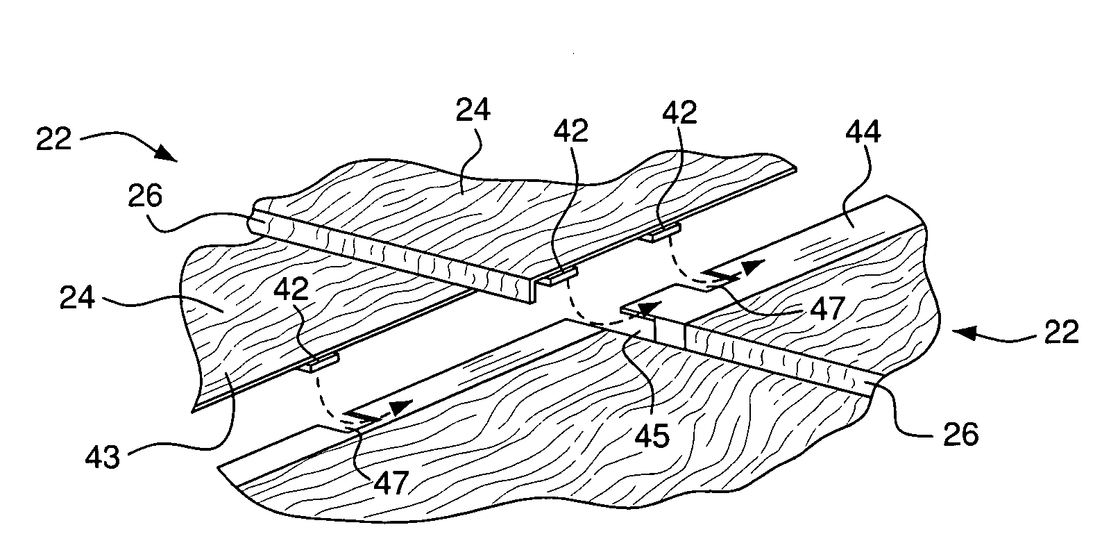
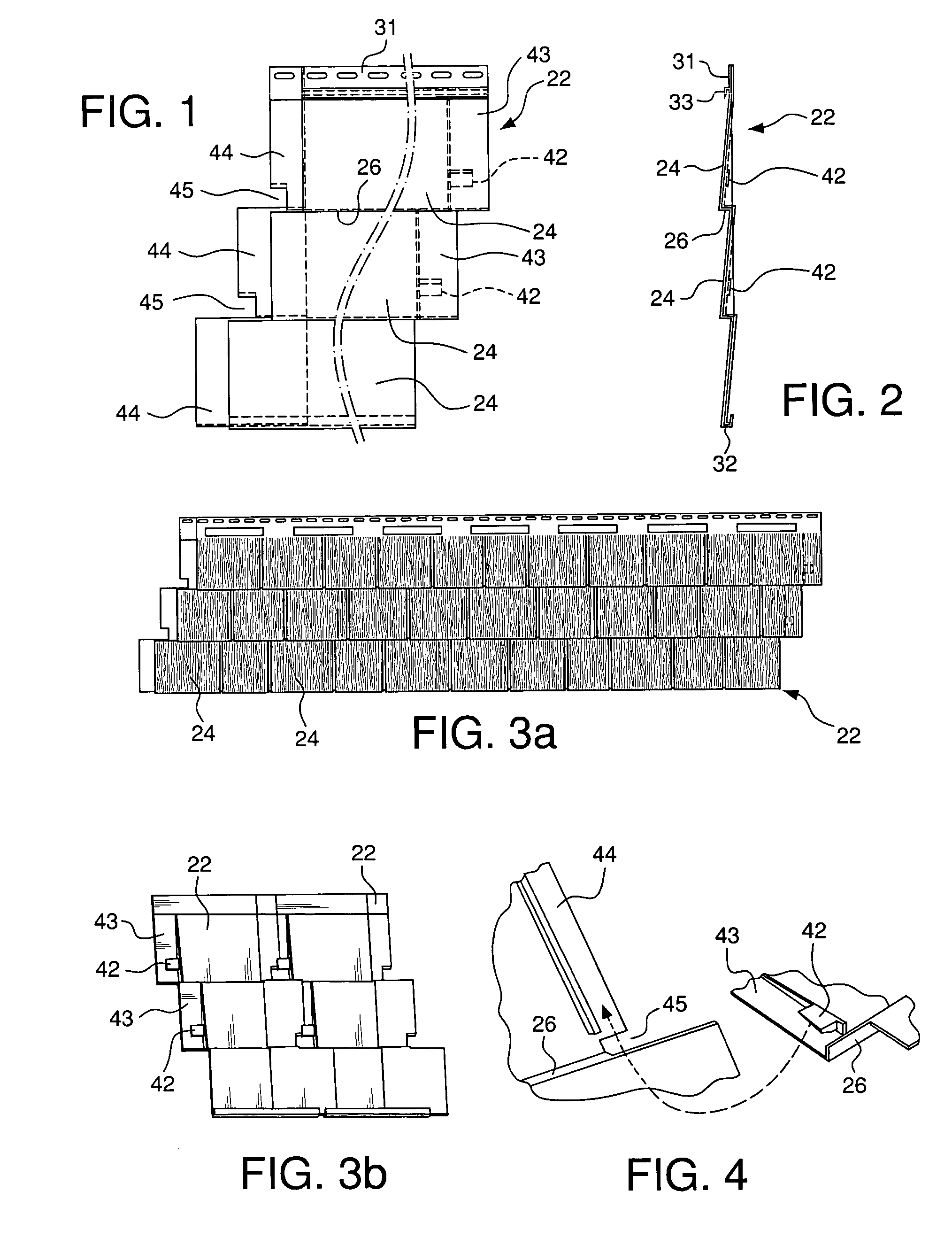
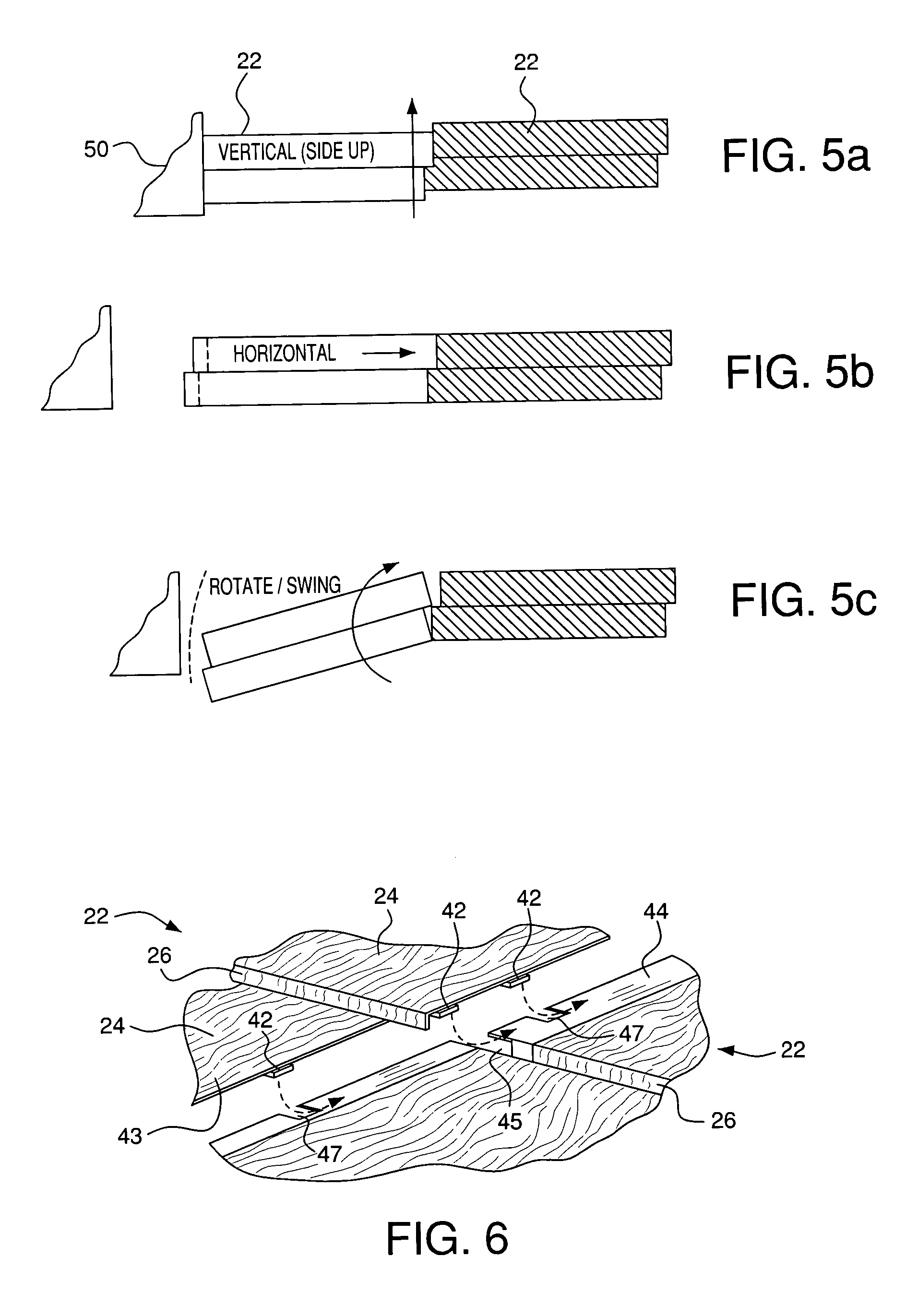
[0048]A number of exemplary embodiments of the invention are described herein with reference to the drawings. These embodiments are examples intended to demonstrate aspects of the invention in different forms or separately. Not all the aspects are required in all embodiments of the invention, and the illustrated embodiments should be regarded as exemplary rather than limiting.

[0049]For example, the illustrative embodiments discussed concern building siding materials of the sort typically installed in horizontally elongated courses on external building surfaces that are vertical and flat. However, the nature of the installation surface and whether or not the courses are elongated horizontally, are subject to variation. For example, the surface could be sloping (such as a roof) or curved. The direction of elongation of the panels could be vertical or inclined instead of horizontal. The application could be an exterior or interior building application or an application that is not rela...


PUM


Abstract

A panel for polypropylene injection molded siding, and for similar materials and / or uses, is mounted in lapped courses with panels attached at butt joints in a direction of elongation. Complementary tabs and slots at the panel ends can be engaged by end-to-end approach of the abutting panels. Additionally, openings for the tabs permit engagement from a position in which the panel ends are already overlapped, which reduces or eliminates the need for endwise assembly space. The slots can be discontinuous on one or both sides, openings permitting lateral insertion of the tabs at gaps, whereupon movement of the tabs along the slots engages the joint. The panels can simulate wood siding and include a step between simulated courses. A gap is provided in the edge of the panel at the step, thus forming an opening for the tab to enter and move along the slot.

Description

BACKGROUND OF THE INVENTION[0001]The invention relates to panels for facing the surfaces of building structures, particularly elongated siding panels installed in lapped courses on exterior walls. In particular, a joint is provided for the ends of abutting panels in a course, with tabs and openings that permit engagement by alternative movements.PRIOR ART[0002]Siding products can simulate traditional materials such as wooden clapboards, cedar shakes and the like. Traditional wood siding materials are installed in overlapped single tiers or courses. Each wood clapboard course typically consists of a row of horizontally elongated planks (clapboards), butted end to end. Similarly, shingle or shake siding typically consists of horizontally aligned rows of single laterally-adjacent shingles or shakes. Except at the extreme top and bottom, each row is overlapped at its top edge by a next higher course, and in turn laps over a next lower course, to the edges of the sided area.[0003]Modern ...

Claims


Application Information

Patent Timeline
Patent Type & Authority Patents(United States)
IPC IPC(8): E04D1/00E04F13/08
CPCE04F13/0864
Inventor STUCKY, DAVID J.SHAW, ROBERT D.STEFFES, STEPHEN W.
Owner CERTAINTEED CORP
Why Eureka
Try Eureka