Fiber-made surface fastener

a surface fastener and fiber technology, applied in the field of fiber-made surface fasteners, can solve the problems of losing the function of the surface fastener, and achieve the effect of excellent softness and never threatening plasticity

Inactive Publication Date: 2007-04-24
THE OHIO STATES UNIV +1
View PDF11 Cites 20 Cited by
  • Summary
  • Abstract
  • Description
  • Claims
  • Application Information

AI Technical Summary

Benefits of technology

[0016]Then, part of the finished yarn is coupled with structure on an opposite side to the side in which loops are formed of a loop woven or knitted fabric and the finished yarn floats on the rear surface of the surface fastener and is exposed except its coupled part, so that it covers substantially entire rear surface of the surface fastener. As a result, the rear surface of the surface fastener in which the finished yarn is exposed obtains an extreme softness feeling, excellent in plasticity and bulking power. At this time, it is necessary to set the weight ratio of the finished yarn to all the warp yarns constituting the ground weave to be 35 to 60% in order to secure plasticity of the surface fastener and secure a softness feeling of the rear surface.
[0018]Because at this time, naturally, the finished yarn floats on the rear surface of the surface fastener while covering the entire surface, the melted yarn material does not permeate the finished yarns so that it is not exposed outside and thus, only part of the composition fibers making contact with weaving or knitting structure on the front surface side of the surface fastener is joined with the weaving or knitting structure on the front surface side of the surface fastener through the melted yarn material. For the reason, the rear surface of the surface fastener after a product is completed still keeps excellent softness feeling. Further, unlike the conventional back coating, there is no necessity of using a large amount of back coating resin as needed in the substrate woven or knitted fabric of the surface fastener and because the composition yarns are joined together effectively inside the substrate, plasticity is never menaced.
[0020]However, according to this weld cutting, its cut end becomes quite hard so that when it hits the skin, it may injure. Thus, in the present invention, to cut such a wide loop woven or knitted fabric to the width of a surface fastener unit, ordinary cutting with a cutter or the like without depending on the weld cutting was considered. However, on a cut section (ear portion) of the above-described weaving or knitting structure, the floating amount of the rear surface is so large, and thus, floating yarn easily ravels out even when it is only hooked by the finger tip, so that napping becomes excessive and as a result, a completed product is incapable of bearing actual use condition. Thus, according to the present invention, preferably, the number of floating (bending) in the ear portion of the substrate woven or knitted fabric of the finished yarn, which strides over the weft yarn or course in the substrate woven or knitted fabric and floats on the rear surface, is set to twice or more the number of floating (bending portions) in the main body portion. By adopting such a configuration, the floating amount of the rear surface in the ear portion is decreased, so that the finished yarn becomes unlikely to ravel out. In this case, by disposing the hot melting yarn as part of the warp yarns disposed in the ear portion as described above, the raveling can be eliminated further.

Problems solved by technology

If an external stress such as cutting or buffing is applied to the loop, whose shape is fixed by thermal setting before the aforementioned cutting or napping, the loop is pulled out or extracted from the substrate woven or knitted fabric, so that it loses the function of the surface fastener.
However, because in each of the fiber-made surface fasteners proposed by the above-mentioned patent documents, the rear surface is not back-coated with various kinds of resins, although plasticity is entirely intensified and the touch feeling on the rear surface is more or less improved, the rear surface makes feel rough and depending on the kind of used yarn, make feel rugged because the number of bending of warp yarn which is bent when striding over weft yarn on the rear surface is quite large.
This is a fatal disadvantage for application in which the rear surface of the surface fastener makes a direct contact with the skin.

Method used


Image

  • Fiber-made surface fastener
  • Fiber-made surface fastener
  • Fiber-made surface fastener

Examples


Embodiment Construction

[0027]Hereinafter, the preferred embodiments of the present invention will be described specifically with reference to examples represented in the figures.

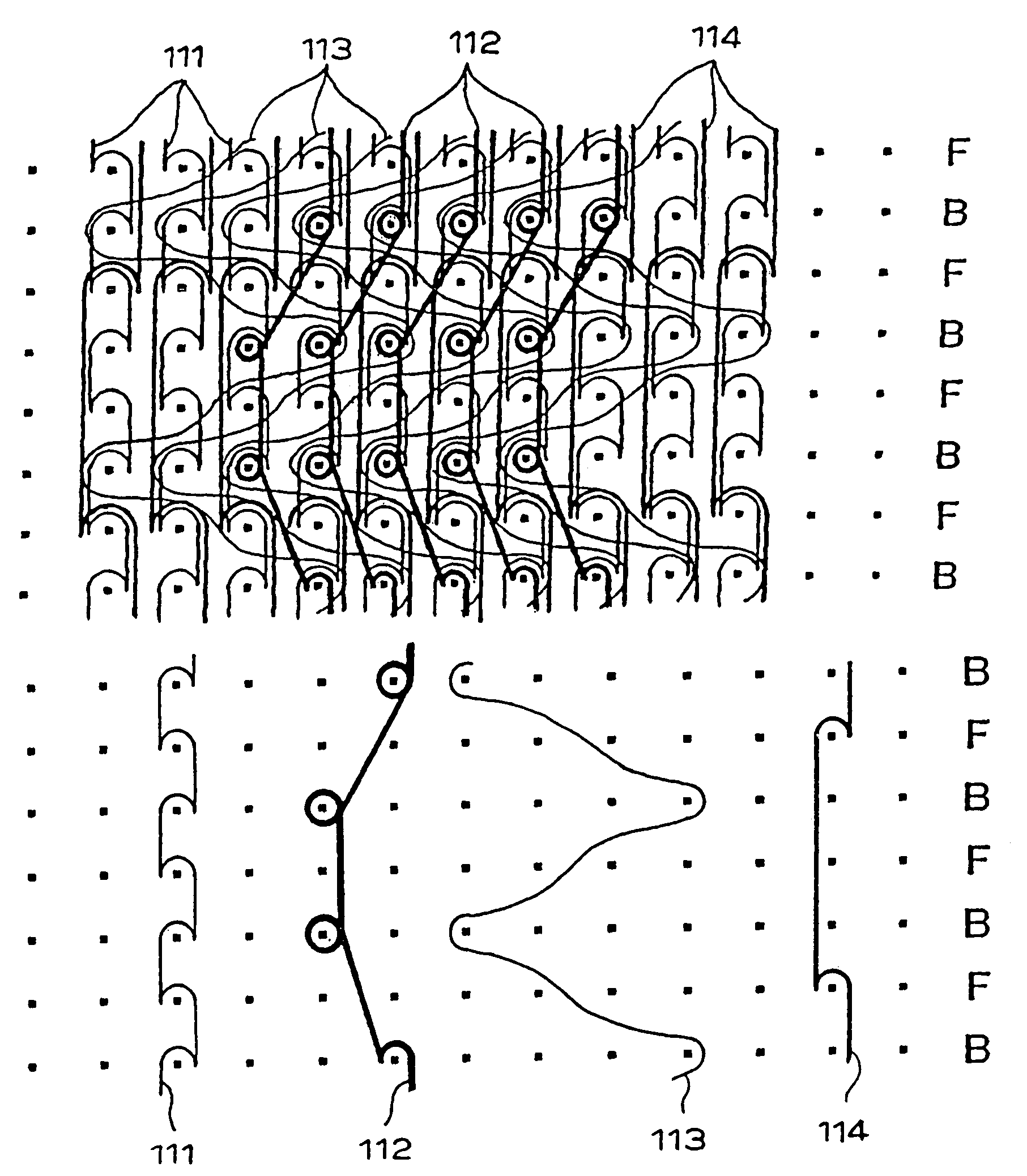
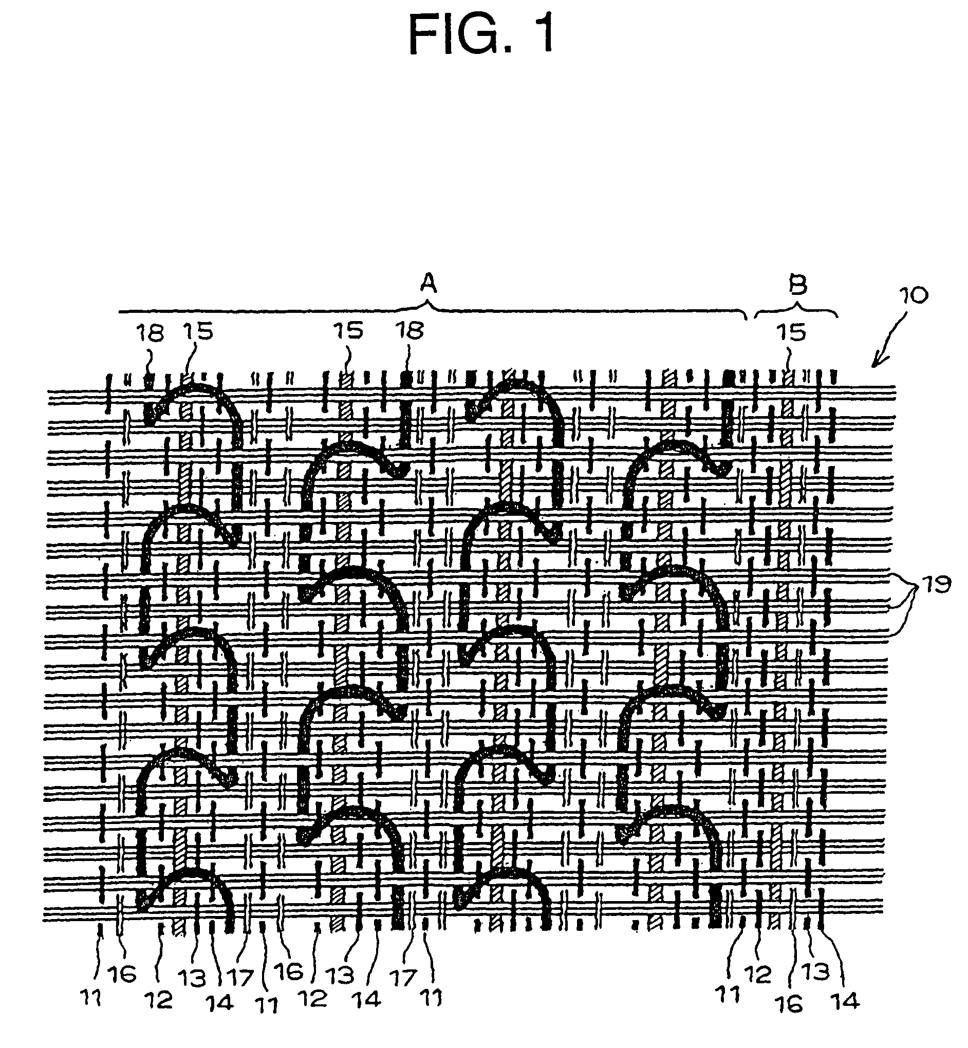
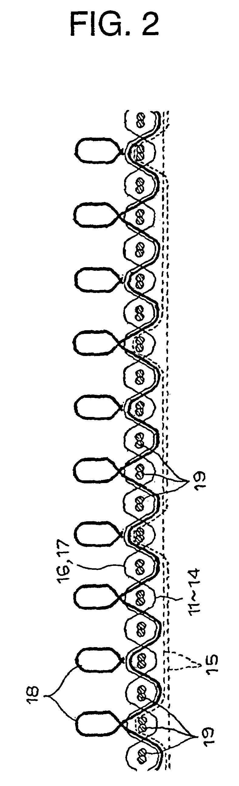
[0028]FIGS. 1 and 2 are weaving structure diagrams showing schematically the first embodiment having a woven fabric structure of a woven surface fastener of the present invention. The same example exemplifies a female surface fastener in which piles composed of a multiplicity of multifilament yarns are formed on a single surface of a substrate woven fabric whose ground weave is composed of the woven surface fastener. In the same figures, reference numeral 10 denotes a substrate woven fabric, reference numerals 11 to 14 denote four warp yarns, first to fourth warp yarns constituting the ground weave of the pile formation side surface, reference numeral 15 denotes a finished yarn floating on the ground weave rear surface on an opposite side to the pile formation side which constitutes part of the characteristic portion of the invent...


PUM


Abstract

A fiber-made surface fastener having on its back a covering of soft fiber yarns excellent in softness and in a function and durability as a surface fastener and including a multiplicity of engaging elements woven or knitted simultaneously with weaving or knitting of a substrate woven or knitted fabric (10) and projecting from a surface of the same woven or knitted fabric (10). Warp yarns (11 to 17, 111, 114) of the substrate woven or knitted fabric (10) contain finished yarns (15, 114) partially. The finished yarns (15, 114) are woven or knitted into the substrate woven or knitted fabric (10) such that the yarn floating from a rear surface of the same substrate woven or knitted fabric (10) and a substantially entire surface of the rear surface of the substrate woven or knitted fabric (10, 110) is covered with the same finished yarns (15, 114). Preferably, these finished yarns (15, 114) are bulky finished yarns composed of multifilaments.

Description

TECHNICAL FIELD[0001]The present invention relates to a fiber-made surface fastener which has engaging elements comprising a multiplicity of loops or hooks, which are woven or knitted into a surface of a woven or knitted fabric obtained by weaving or knitting at the same time of weaving or knitting the same woven or knit fabric.BACKGROUND ART[0002]This kind of fiber-made surface fastener is, generally, manufactured of so-called pile woven or knitted fabric having a multiplicity of loops erected from a surface of a flat substrate woven or knitted fabric, the substrate woven or knitted fabric generally composed of a ground weave of a fiber-made woven fabric or knitted fabric. Usually, after loop (pile) yarn composed of monofilament is woven or knitted simultaneously with the weaving or knitting of the substrate woven or knitted fabric constituting the ground weave, a hook piece is produced by cutting partially a side portion of each loop, or after a top portion of the loop is cut out,...

Claims


Application Information

Patent Timeline
Patent Type & Authority Patents(United States)
IPC IPC(8): D04B23/08A44B18/00
CPCA44B18/0023D04B21/02D04B21/20D03D1/00D10B2403/0114D10B2501/0632
Inventor OKAWA, MITSUHISA
Owner THE OHIO STATES UNIV
Why Eureka
Try Eureka